The electronics side of the project was where I started to hit some bumps in the road from the original article.
First of all, although the article contains a list of required components, I don't think it's fully accurate.
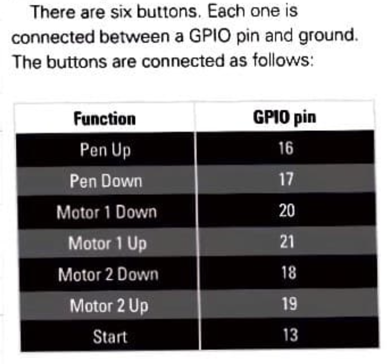
Exhibit A:

... so that's 7 buttons, then 🤓
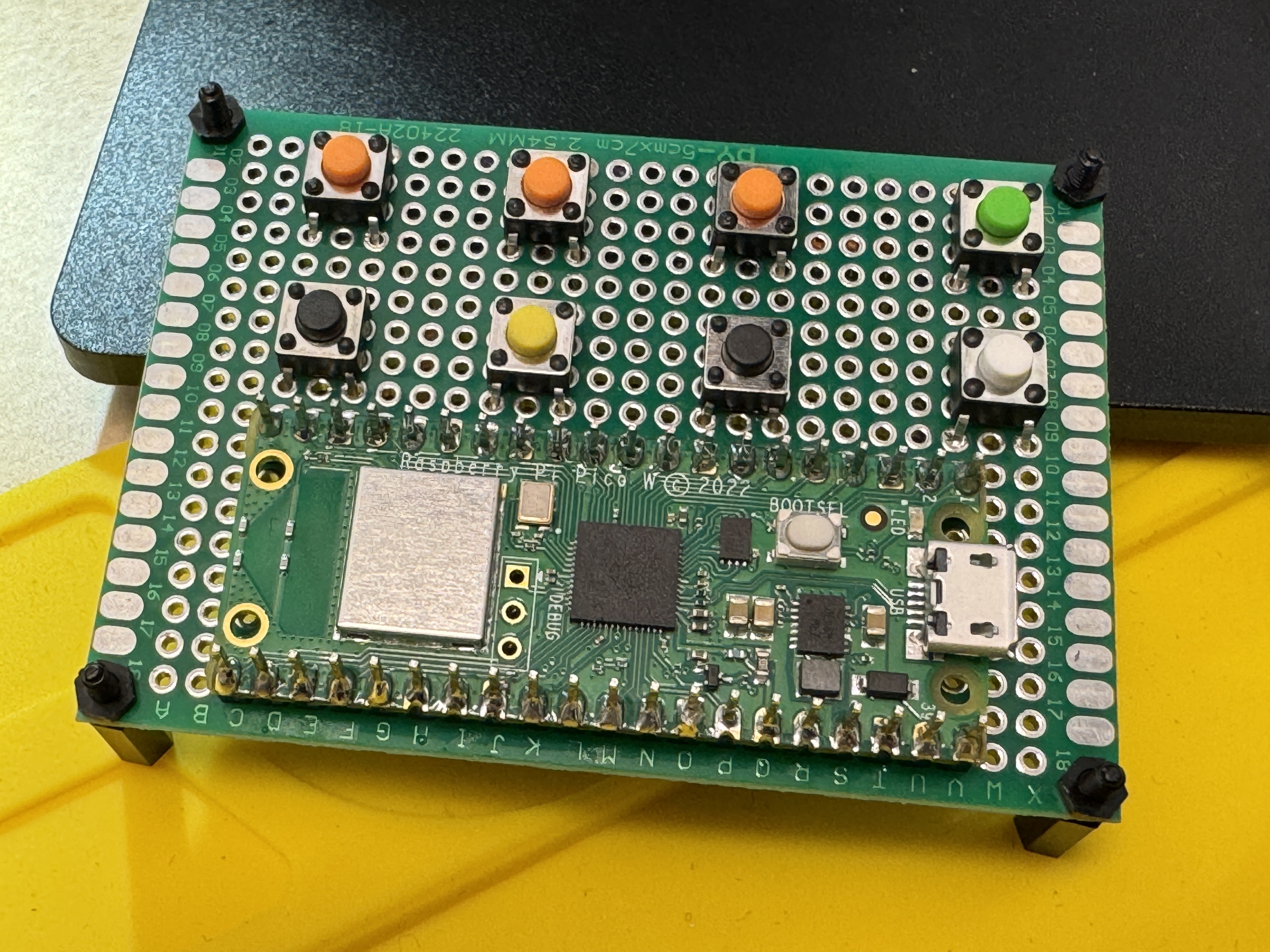
I've mounted the Pico (W) on a protoboard and laid out 7 buttons, with a bit of colour-coding since I had some coloured ones to hand - orange for the "up" buttons, and green for "start". After a bit of testing with the firmware, I also added an 8th button as a broken-out reset for the Pico.

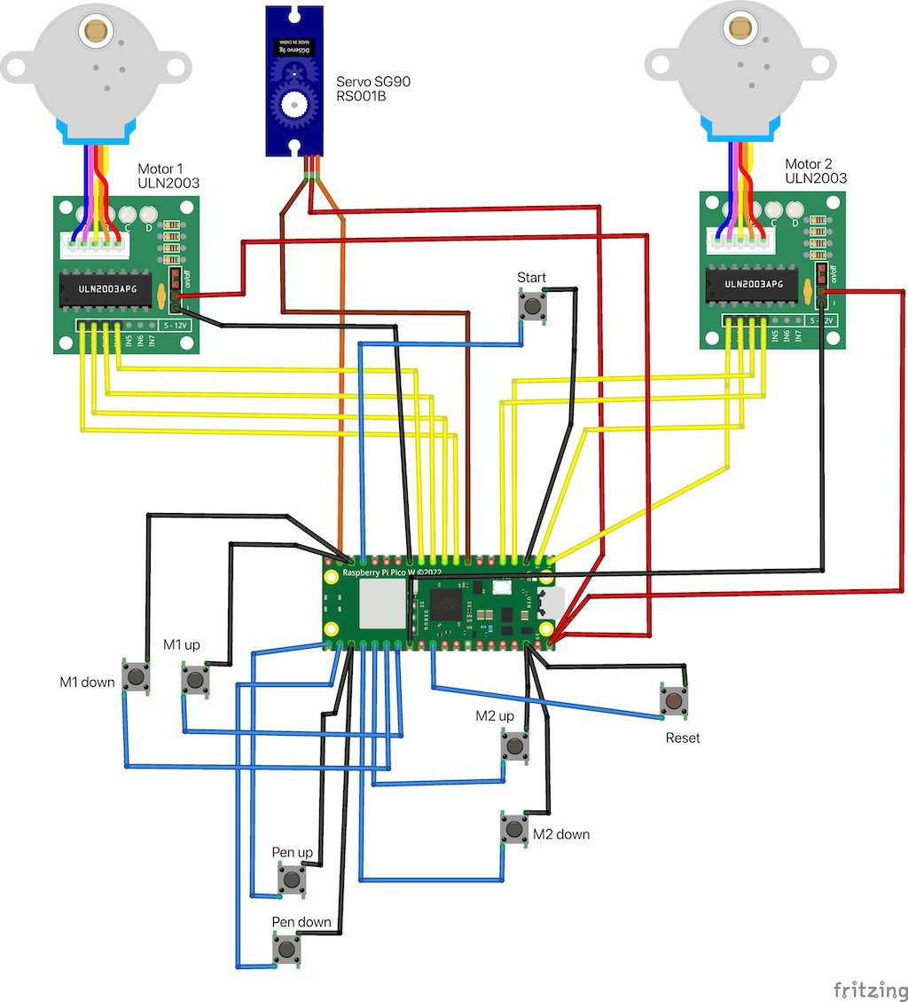
I also decided to make a diagram to help me to sort out the wiring, since the original project didn't contain one (although it does helpfully explain which pin connects to what, as above). I created this using Fritzing, which needed me to track down parts for the Pico W and the motors. The Fritzing sketch is inside my fork of the original GitHub project, on the pico-w-build branch.

A possible future revision could include a nicer, possibly custom-designed PCB to contain the Pico, the buttons, and maybe even with space for the ULN2003 motor drivers to be attached so that it's an all-in-one control panel. Just an idea.
 Andy Piper
Discussions
Become a Hackaday.io Member
Create an account to leave a comment. Already have an account? Log In.