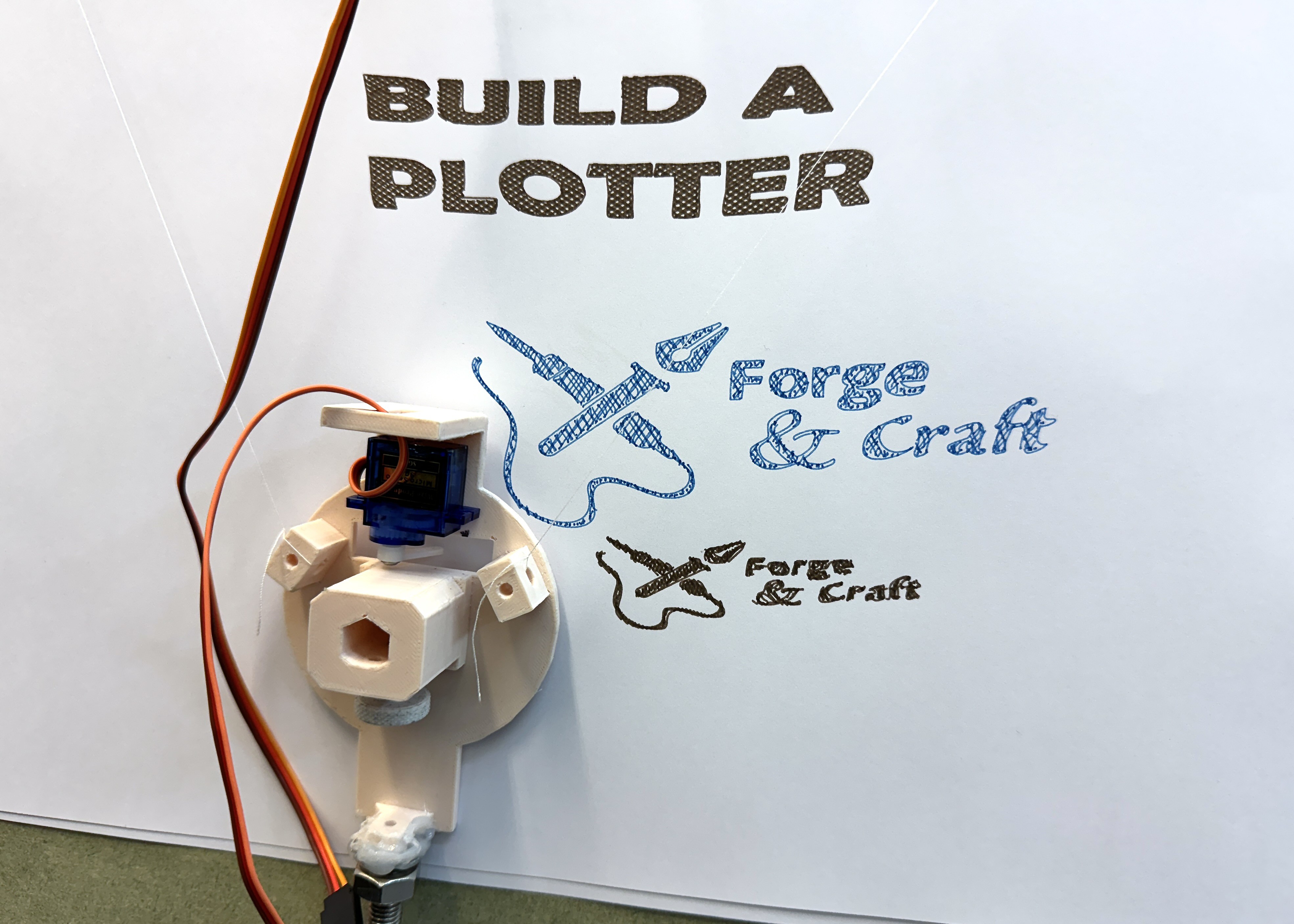
In the previous test, I was getting output, but the alignment and direction was all wrong.
After several iterations (switching m1<->m2 wiring, and also, diving back into the firmware code), I figured out that the firmware needed to be set up to invert one of the motors.
#define INVERT_M1_DIR     1 // -1
#define INVERT_M2_DIR     -1 // -1
I also needed to tune the angle for the servo to ensure that the pen was properly lifted. Merged into my fork of the original code.
There have also been a few annoyances with the wiring (the Dupont cables kept popping apart where I'd extended things so I lost power to one of the motors midway through a plot, for example). Also, motor 2 seemed to be slipping / not moving as smoothly as motor 1... I think I've now resolved that by reseating all of the connections. Lots of tidying up to do.

CNCjs has worked out well to drive the plotter. For the studio logo, I took an existing SVG, broke it down into paths, used the AxiDraw plugin for Inkscape to add hatching to fill, repositioned the whole thing over the corner of the page (because the plotter expects a centre-aligned image), and used Ben's fork of gcodeplot to output a gcode file that I could use with the plotter. It looks like gcodeplot could actually send the commands directly to the printer, as well.
I'm happy that I've got to here from the original article and materials i had to hand! There are a number of things I want to work on next:
Hardware:
- print a better holder for the electronics. Right now, the ULN2003 motor drivers are barely attached to the board with electrical tape, and keep falling off... not ideal.
- (possibly) switch to a better thread, or, would fishing line be good here?
- trim the board to a size that works for the whole setup (I can take off about 50-60cm without impacting the drawing area; I think I'll go to 60, which will leave me with a square 60x60cm MDF board)
- mount the board on the wall of the studio.
Firmware:
- the original, original code had support for reading a file from SD card. I have a microSD adapter board which I could wire up.
- I have a Pico W here, so I could be accessing it wirelessly...
- should I try this in MicroPython? that would mean rewriting all of the tricky gcode handling code, which I haven't had to go near so far.
- so if I have serial, SD card or wifi inputs, I would need a mode switch of some kind to select how the plotter should expect to be driven.
... and then if we start thinking about mode switches, I might need to redo the electronics, and then I might want a board that takes a Pico as a controller, with the motor drivers and buttons attached... and hey, I've built a CNC machine. And we are back to "why am I not using GRBL/grblHAL here?". Well, because this is interesting.
For something that was intended as a learning exercise, I've learned a lot, and have different directions I can go! I'm not marking this as completed just yet, but I count it as "mostly done".
 Andy Piper
Discussions
Become a Hackaday.io Member
Create an account to leave a comment. Already have an account? Log In.