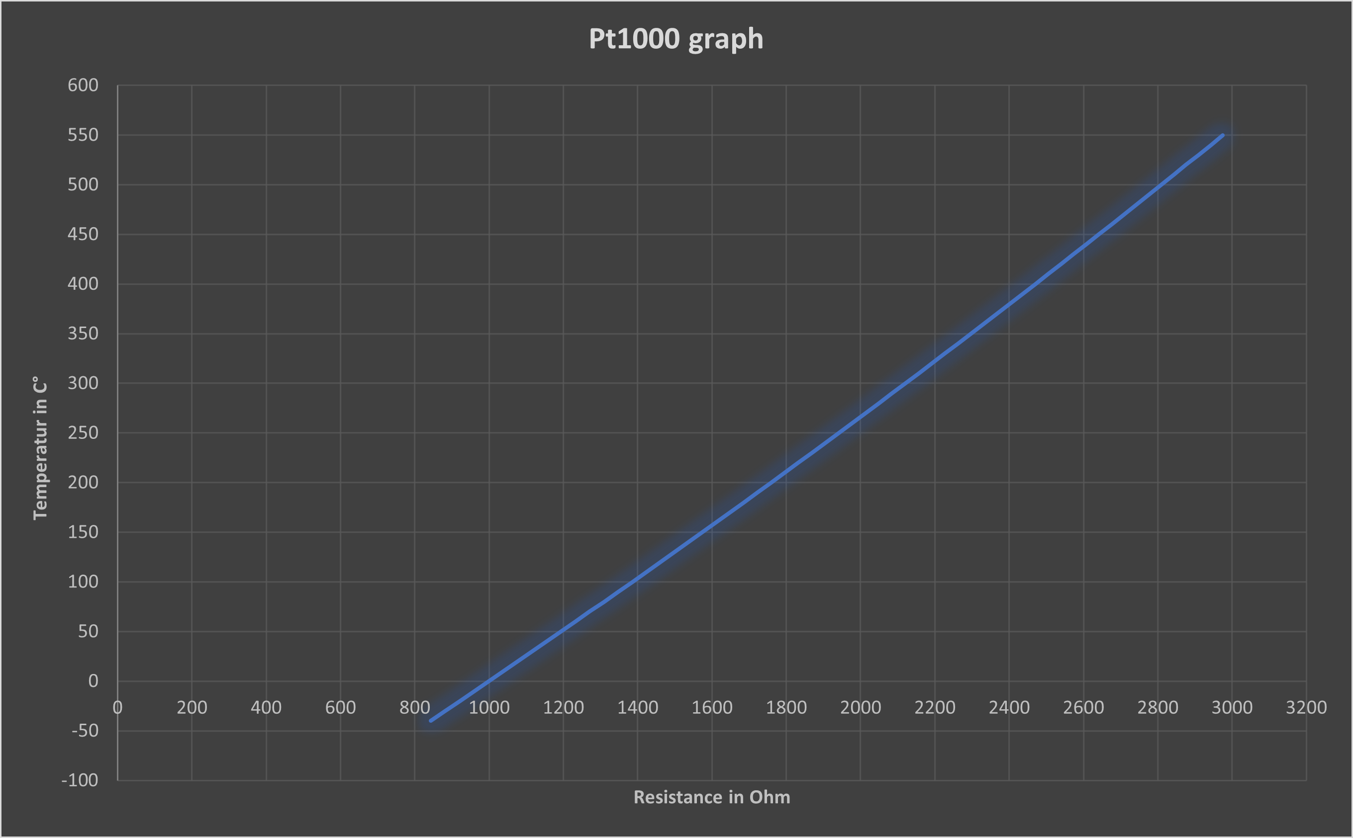
The characteristic curve of the Pt1000 is as follows:

Fig. 1
It can be assumed to be a good approximation of a straight line. However, we can do little with this, as the microcontroller measures the voltage at the output of the opamp. The microcontroller maps the input voltages between 0 and 5 V to integer values between 0 and 1023. We do not need to convert the measured voltage back into volts, it is sufficient to make a note of the analogRead() values. During the measurements, the Pt1000 is simply replaced by a potentiometer whose resistance is set according to the characteristic curve of the Pt1000 so that it corresponds to a certain temperature, for example, 1000 Ω at 0 °C and 1385 Ω at 100 °C.

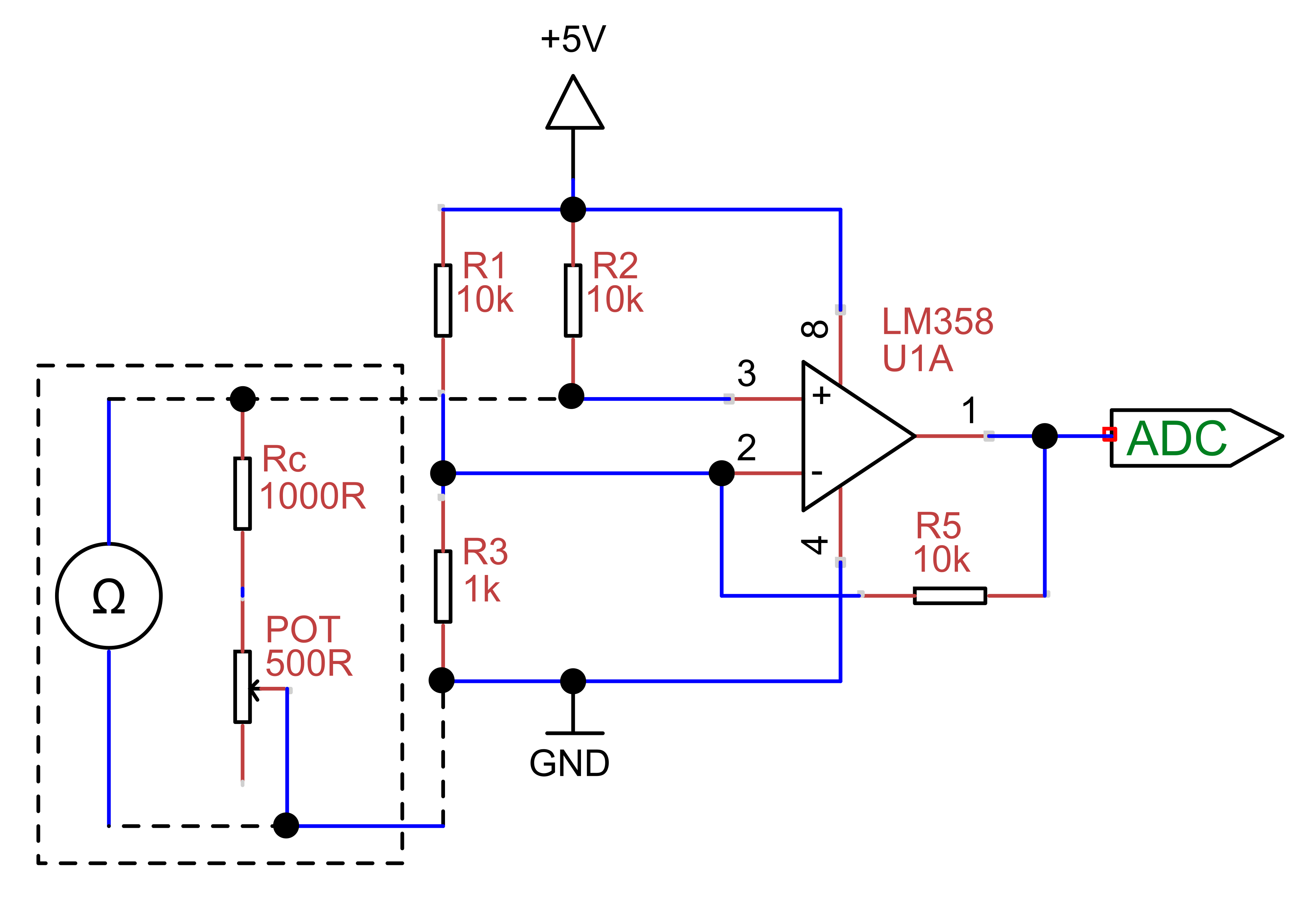
Fig. 2
If we assume in the best case that the analogRead() value is also linearly dependent on the temperature, two measuring points are sufficient and we can determine the corresponding linear equation using the two-point form:
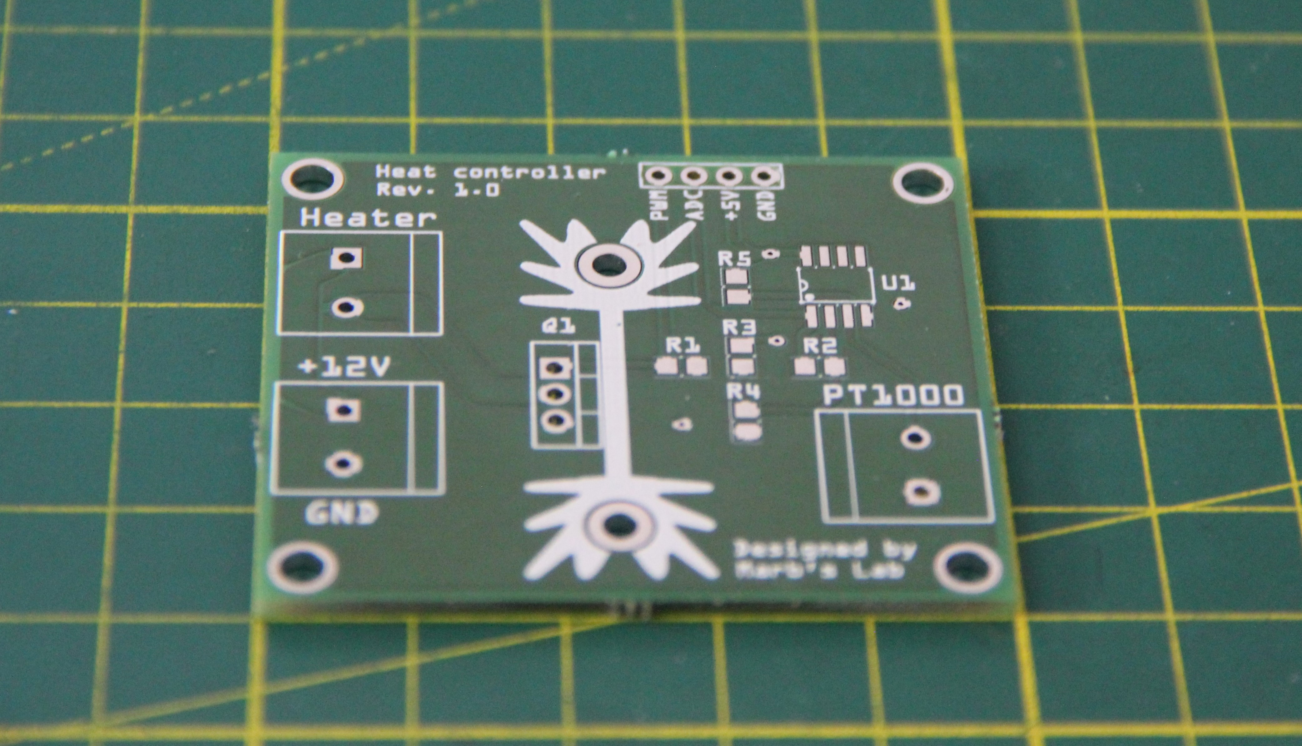
A PCB was designed according to Fig. 2, with an additional logic level n-channel power MOSFET (RFP30N06LE) for switching the heating cartridge.

Fig. 3

Fig. 4
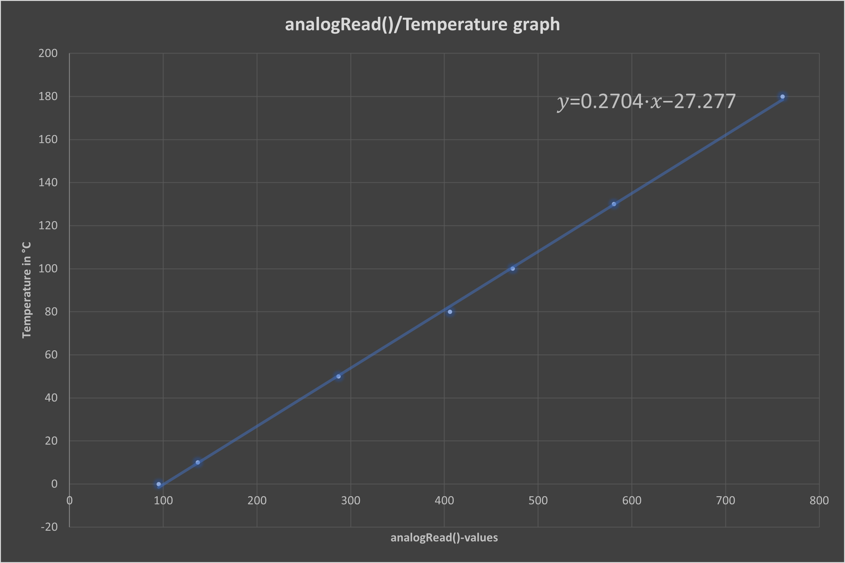
After a few measurements, it is clear that our assumption of linearity is correct.

Fig. 5
Using linear regression, the following function is obtained:
The maximum value of the analogRead()-value for this opamp configuration is 764, which corresponds to 3.73 V (10-bit ADC resolution, 5 V-microcontroller).
Unfortunately, the Pt1000 I bought does not correspond to the characteristic curve in Fig. 1. I then noted the analogRead()-values at 100 °C and 12°C. To do this, the sensor was immersed in water at the corresponding temperatures (I used a laboratory thermometer to measure the water temperature), and the function was recalculated:
In the meantime, I have developed the glucose receptor a little further. It was mounted on an aluminum plate and fitted with two heat sinks.

Fig. 6
I am using a PID algorithm to control the temperature. The code is mainly adapted from here.
// Pins
int PWM_pin = 9;

// Variables
float temperature_read = 0.0;
float set_temperature = 100;
float PID_error = 0;
float previous_error = 0;
float elapsedTime, Time, timePrev;
int PID_value = 0;

// PID constants
int kp = 15.0;   int ki = 0.3;   int kd = 1.8;
int PID_p = 0;    int PID_i = 0;    int PID_d = 0;


void setup() {
  Serial.begin(9600);
  pinMode(PWM_pin,OUTPUT);
  // Set timer 2 divisor to 32 for PWM frequency of 980.39 Hz
  // on pin D9 and D10 (Arduino Mega)
  TCCR2B = TCCR2B & B11111000 | B00000011;
  Time = millis();
}


void loop() {
  // First we read the real value of temperature
  int AD_C = 0;
  AD_C = analogRead(0);
  temperature_read = 0.3548 * AD_C - 45.839;
  // Next we calculate the error between the setpoint and the real value
  PID_error = set_temperature - temperature_read;
  // Calculate the P value
  PID_p = kp * PID_error;
  // Calculate the I value in a range on +-3
  if(-3 < PID_error <3)
  {
    PID_i = PID_i + (ki * PID_error);
  }
  // For derivative we need real time to calculate speed change rate
  timePrev = Time; // the previous time is stored before the actual time read
  Time = millis(); // actual time read
  elapsedTime = (Time - timePrev) / 1000;
  // Now we can calculate the D calue
  PID_d = kd*((PID_error - previous_error)/elapsedTime);
  // Final total PID value is the sum of P + I + D
  PID_value = PID_p + PID_i + PID_d;
  // We define PWM range between 0 and 255
  if(PID_value < 0)
  {    PID_value = 0;    }
  if(PID_value > 255)
  {    PID_value = 255;  }
  // Now we can write the PWM signal to the mosfet on digital pin D9
  analogWrite(PWM_pin, PID_value);
  Serial.println(PID_value);
  previous_error = PID_error; // Remember to store the previous error for next loop.
  delay(300);
  Serial.print("Set temperature: ");
  Serial.println(set_temperature);
  Serial.print("Real temperature: ");
  Serial.println (temperature_read);
  Serial.println("");
}
The constants must be determined experimentally.
 M. Bindhammer
Discussions
Become a Hackaday.io Member
Create an account to leave a comment. Already have an account? Log In.