The biggest risk on the mechanical side of the project is backlash and flex in the assembly.
Backlash is difficult to account for in control systems so it's better to tackle it at the source.
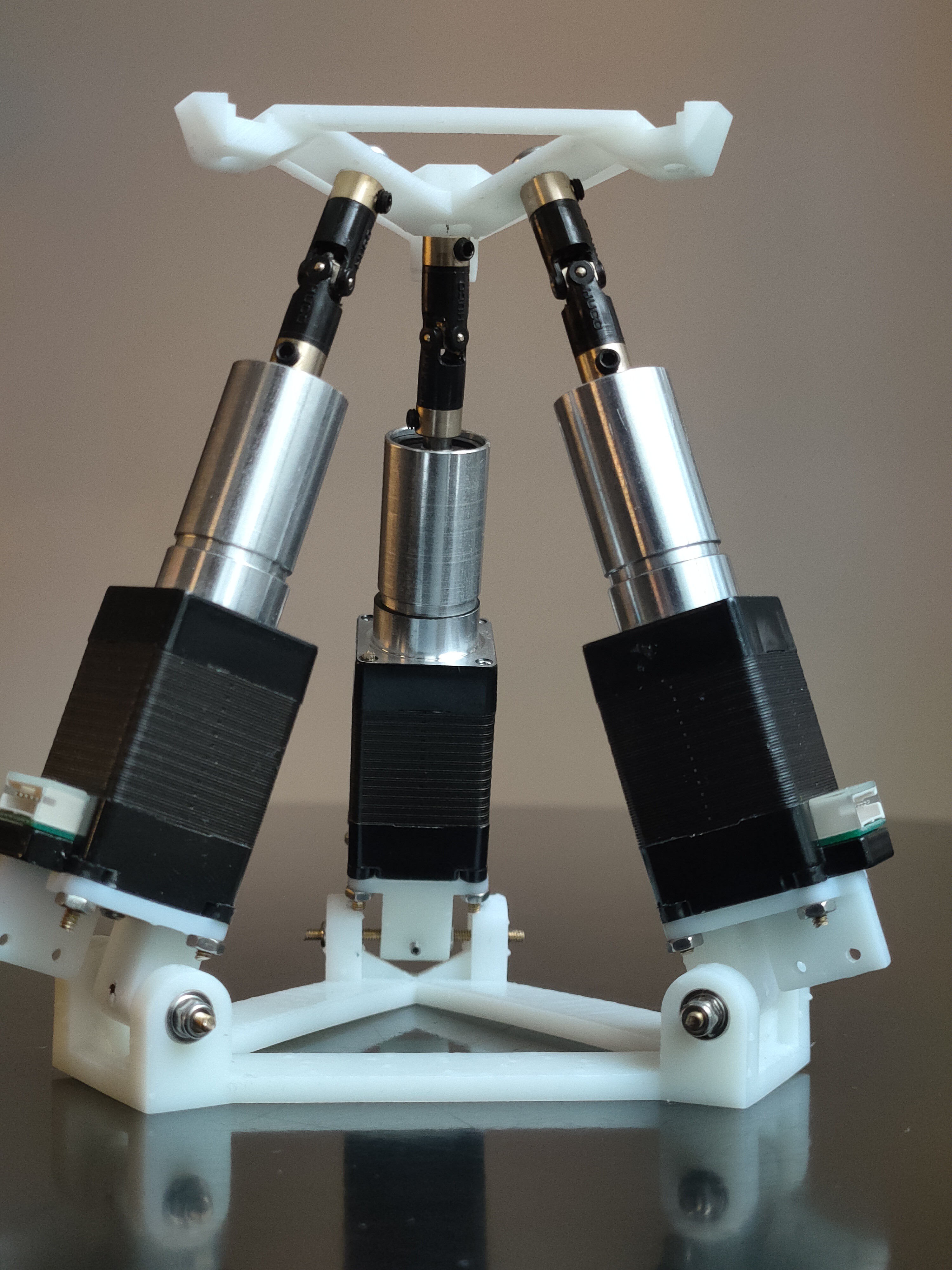
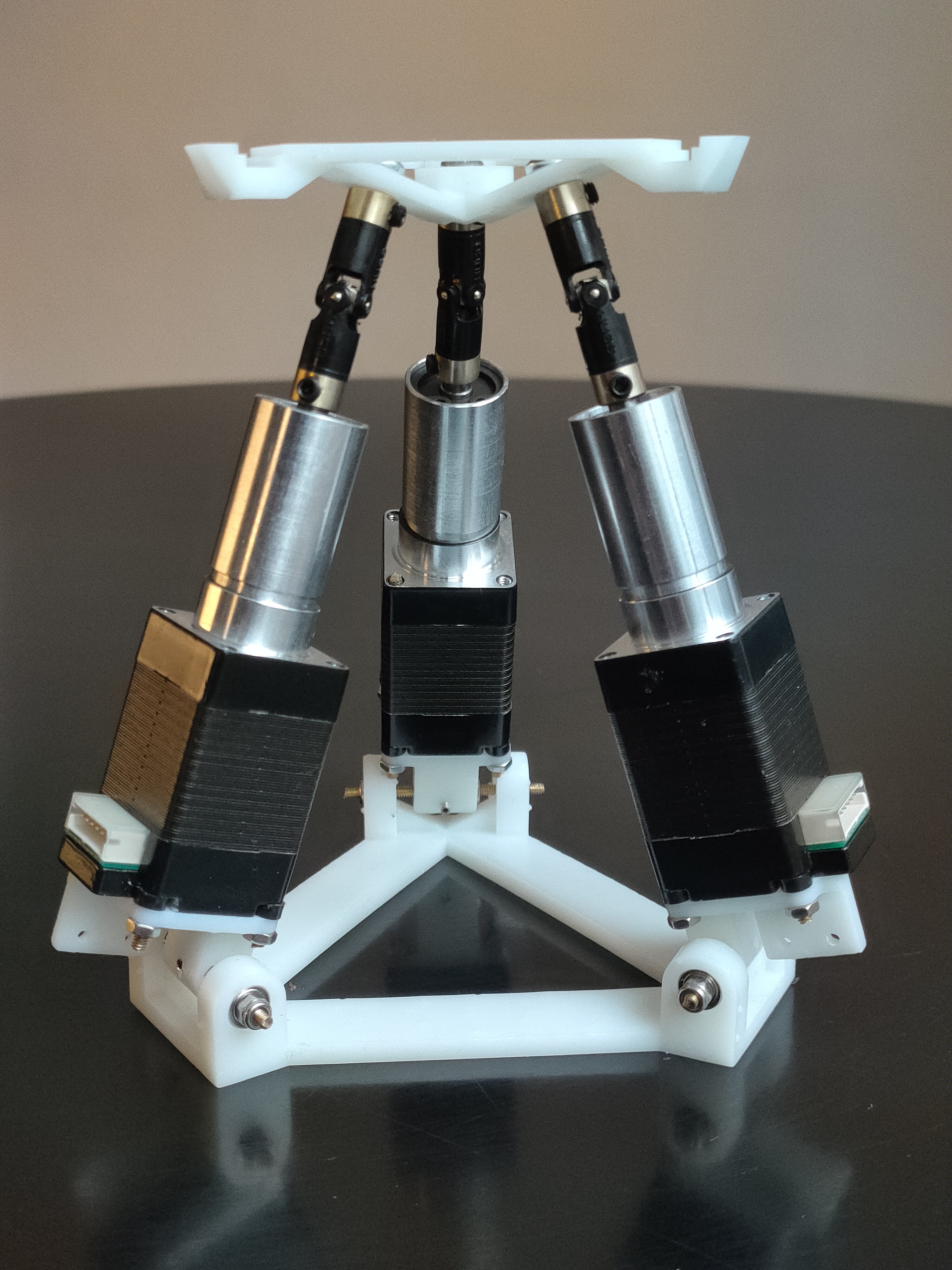
To make the build I SLA resin printed all non standard parts, here you can see the results:


There were no major issues with assembly, however there were some issues with backlash and flex. On the video you can see me stressing the assembly to see where the weak points are.
I found the following issues:
- The base of the assembly is not too sturdy, introducing a lot of flexing
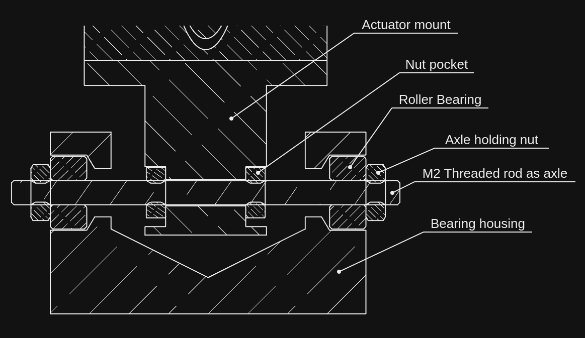
- The axle of the actuator mount is an M2 threaded rod, which has a slightly smaller outer diameter than 2mm (0.079 inches).

- The M2 axle is not particularly rigid, so it introduces some amount of flex as well.
- The plate holding bracket has some axial play introducing some backlash.
Other observations:
- The actuator could be mounted 180 degrees around, so that cabling wouldn't need to go around it to meet in the middle.
- It's pretty and I'm very happy with it
These issues will be tackled in the next version (BJR_02) but it's not severe enough to stop in my tracks to continue.
 Tamas Feher
Discussions
Become a Hackaday.io Member
Create an account to leave a comment. Already have an account? Log In.