 Michael Gardi
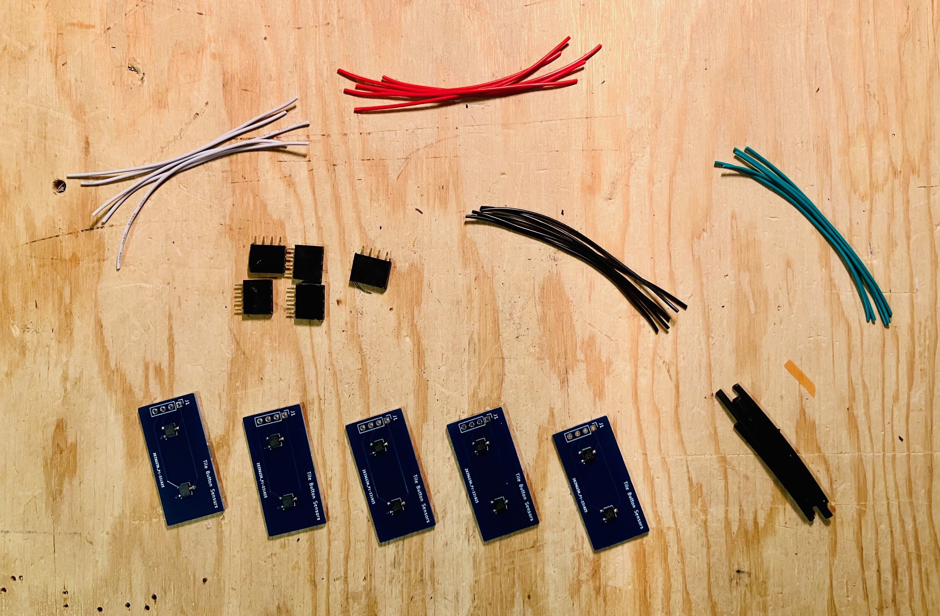
I'm using standard pitch female headers to make connectors for the tile buttons. I cut a longer header into 4 pin lengths. I found it easier to attach the wires to the header before attaching them to the button.
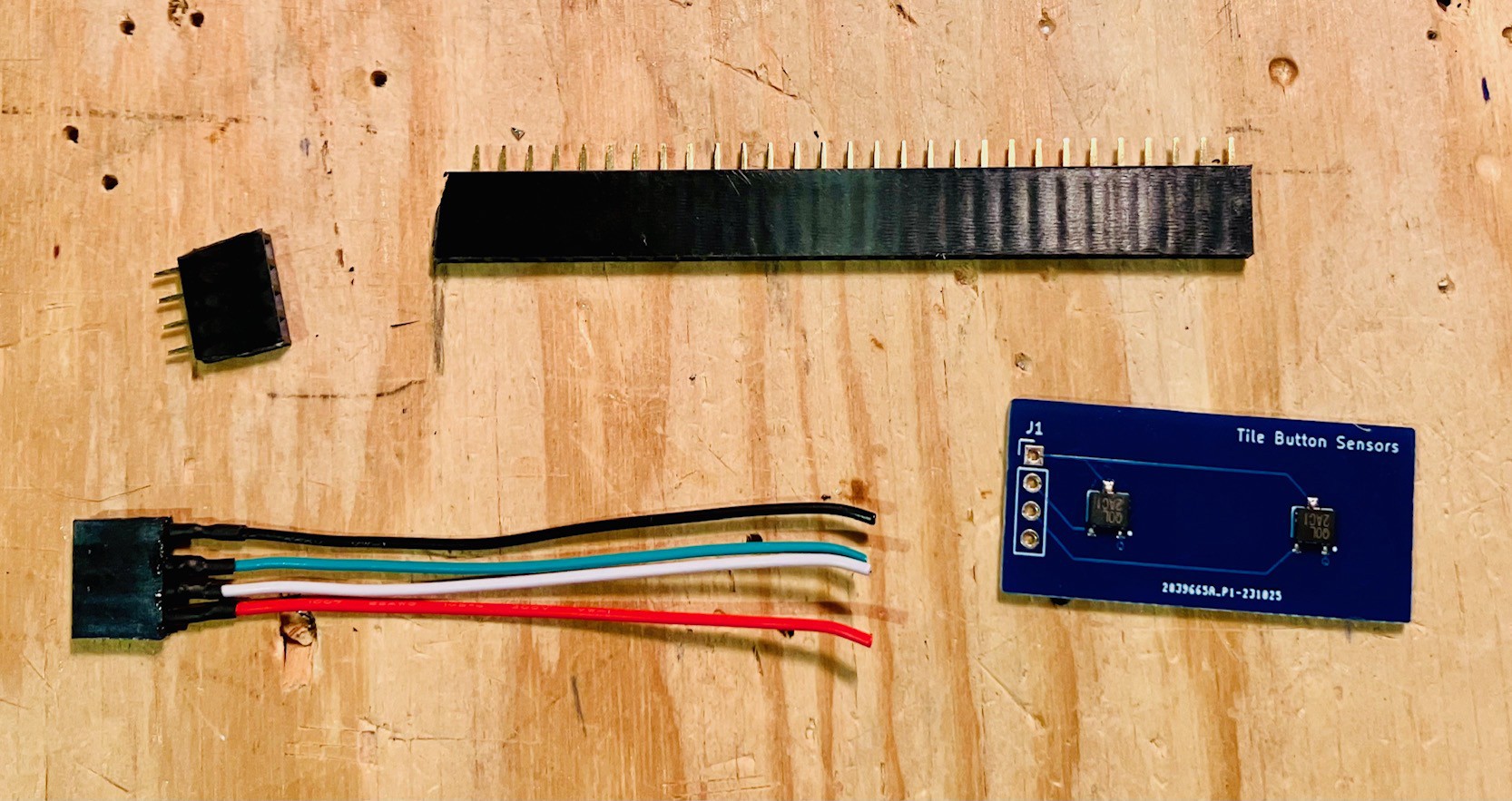
Above you can see the header connector attached to four wires that are about 65 mm in length. I used some heat shrink tubing to prevent shorting and to further secure the connector. Then solder the wires to the sensor PCB from below as pictured below.
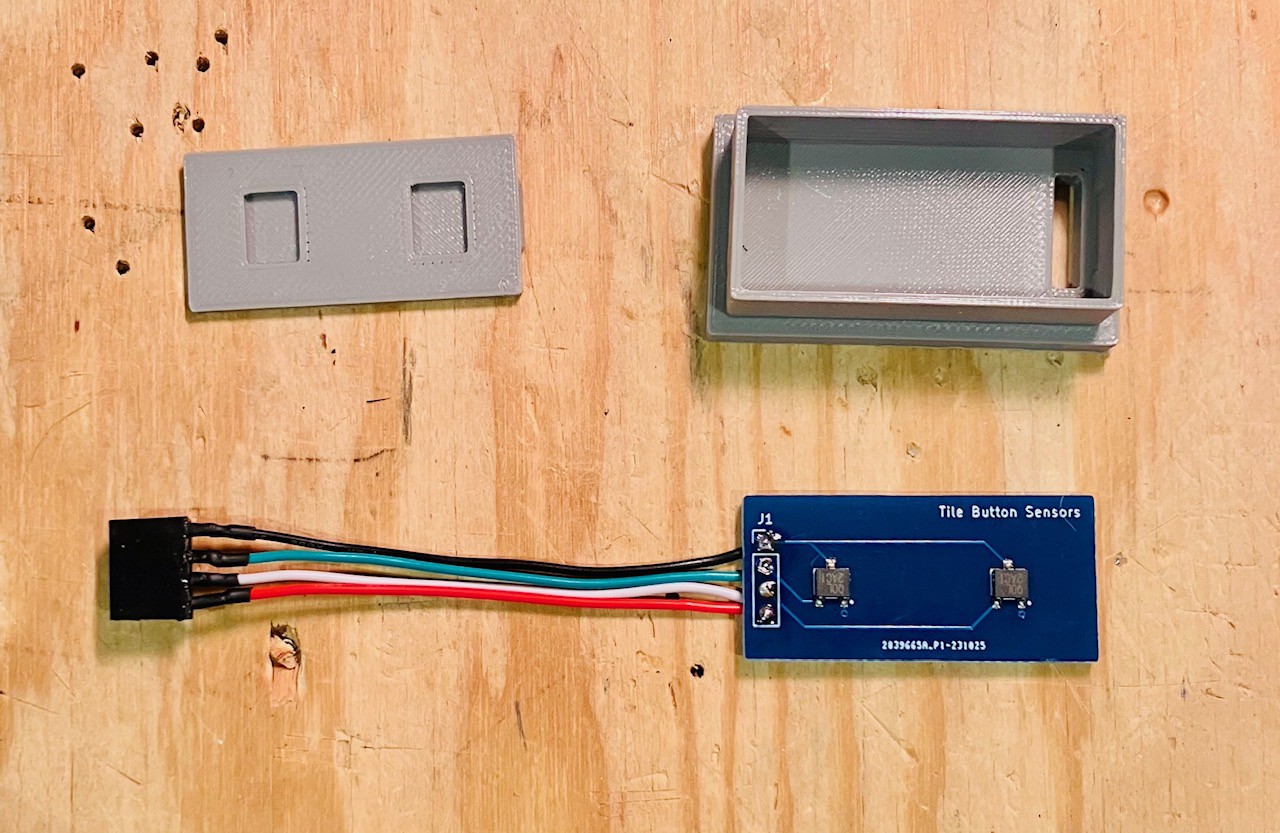
Now assemble the tile holder button as described in the PCB Tile Holder Buttons log.
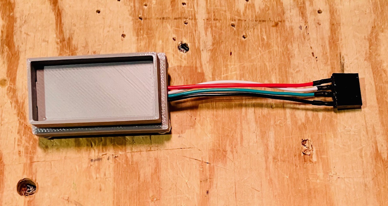
Then a quick test.
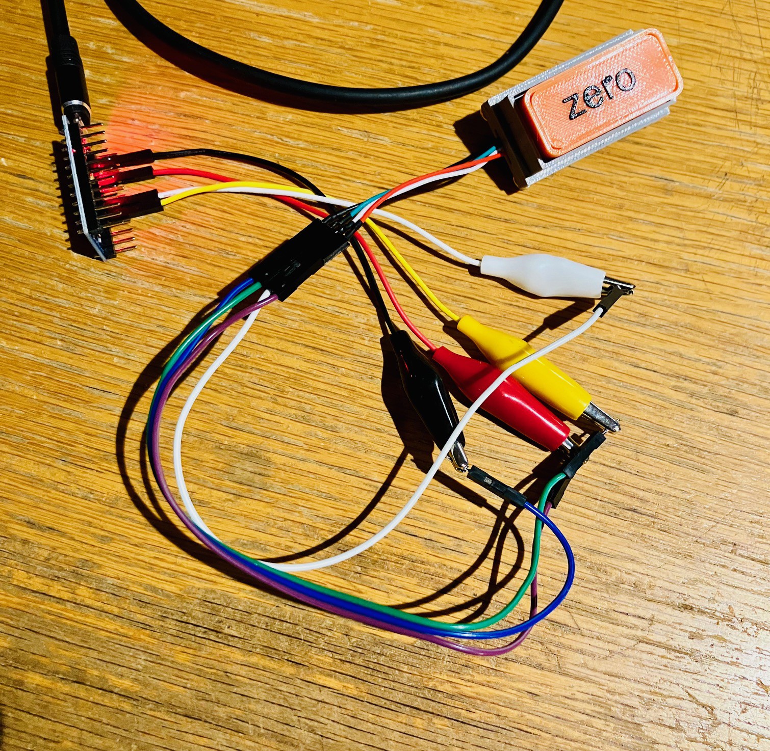
And on to the next. Time for some assembly line work.
Imagine a fast forward video of me assembling these button holder sensor units.
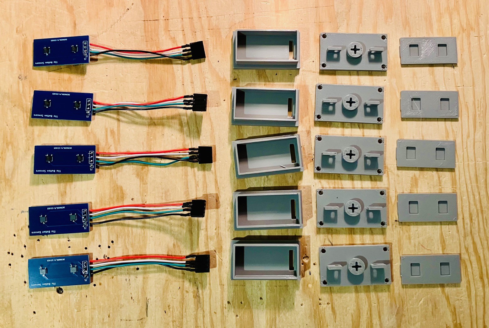
Again assemble the remaining five tile holder buttons as described in the PCB Tile Holder Buttons log.
Discussions
Become a Hackaday.io Member
Create an account to leave a comment. Already have an account? Log In.