Close
0%
0%

Dirt Cheap Tube Guitar Amp Build

Building my first tube amplifier, on a tight budget.

Similar projects worth following
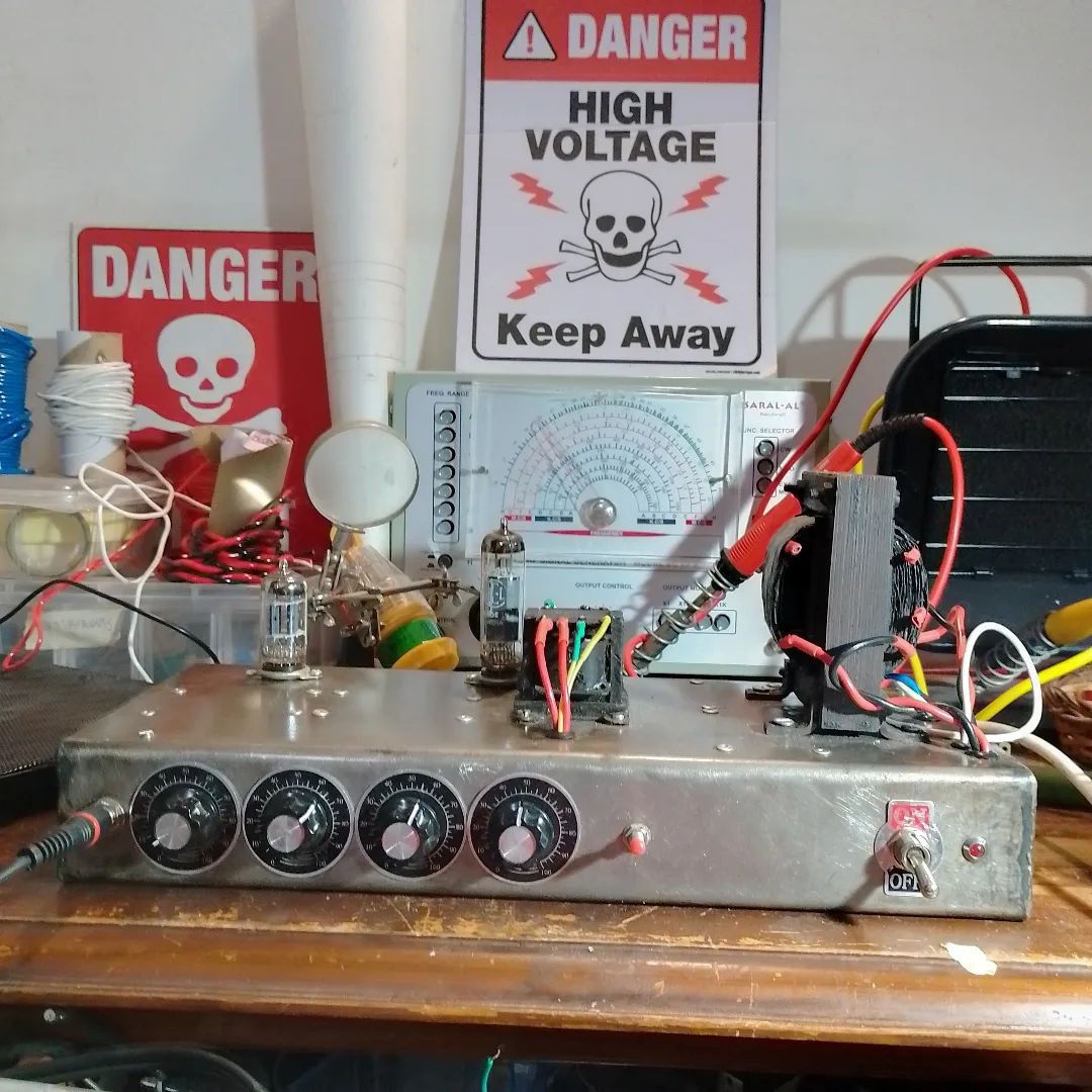
The goal of the project was to learn about the functioning and construction of vacuum tube amplifiers by building and analysing a simple guitar amplifier on a tight budget, using salvaged parts. The amp was built in using traditional point-to-point wiring.

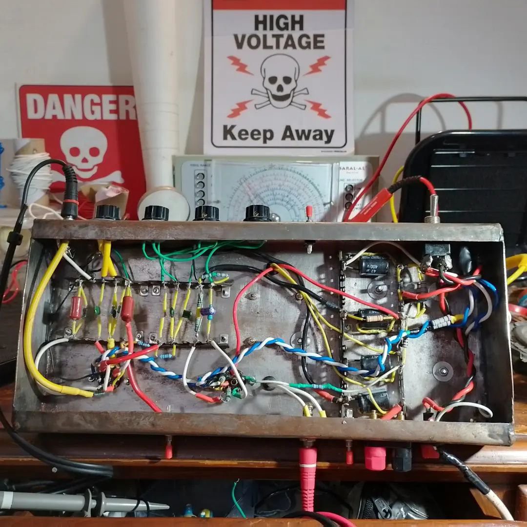
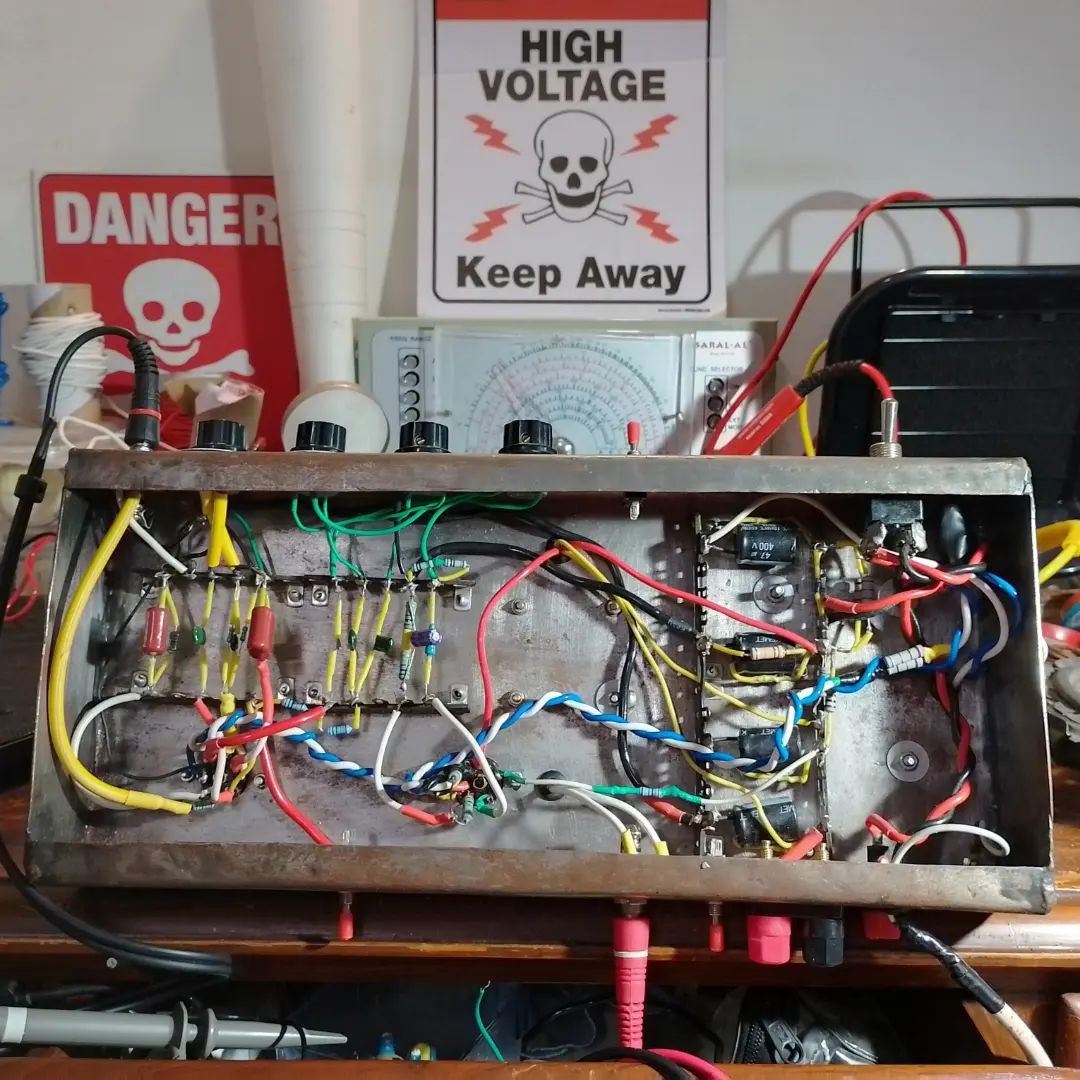
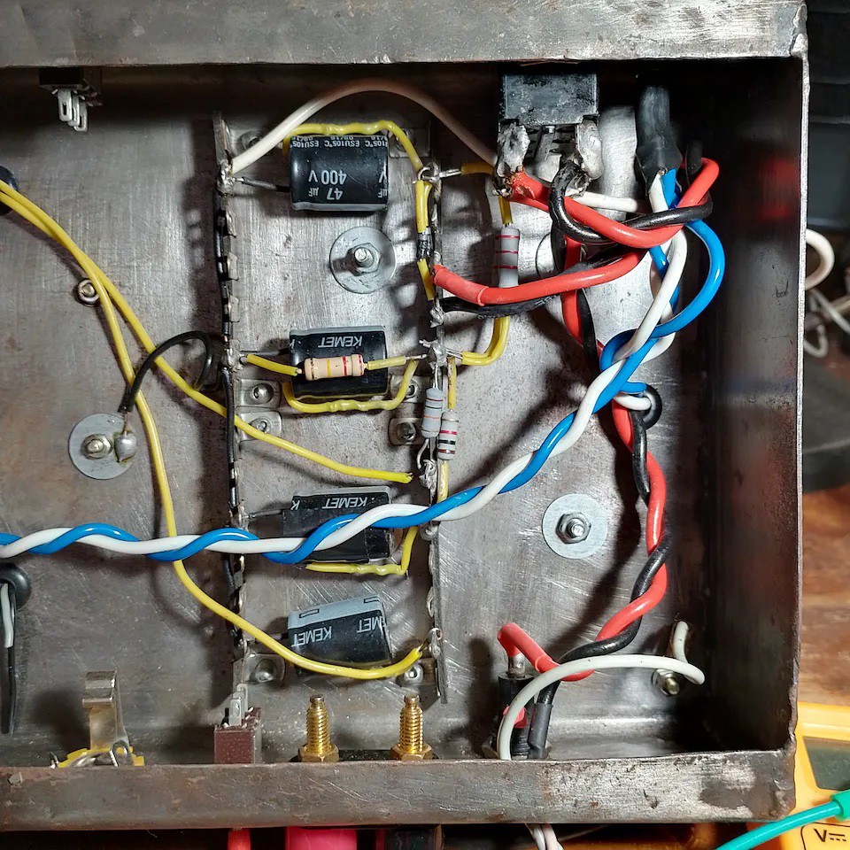
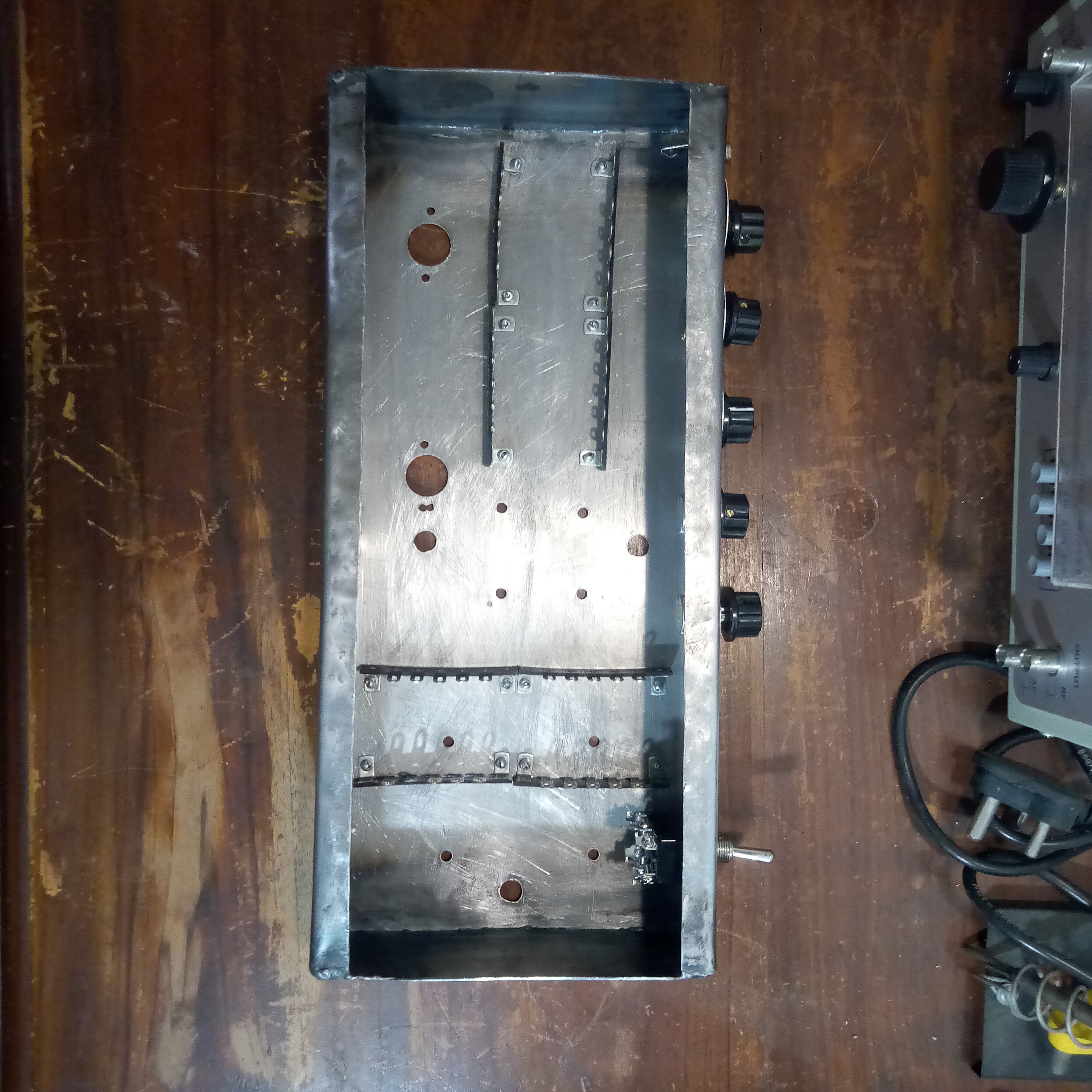
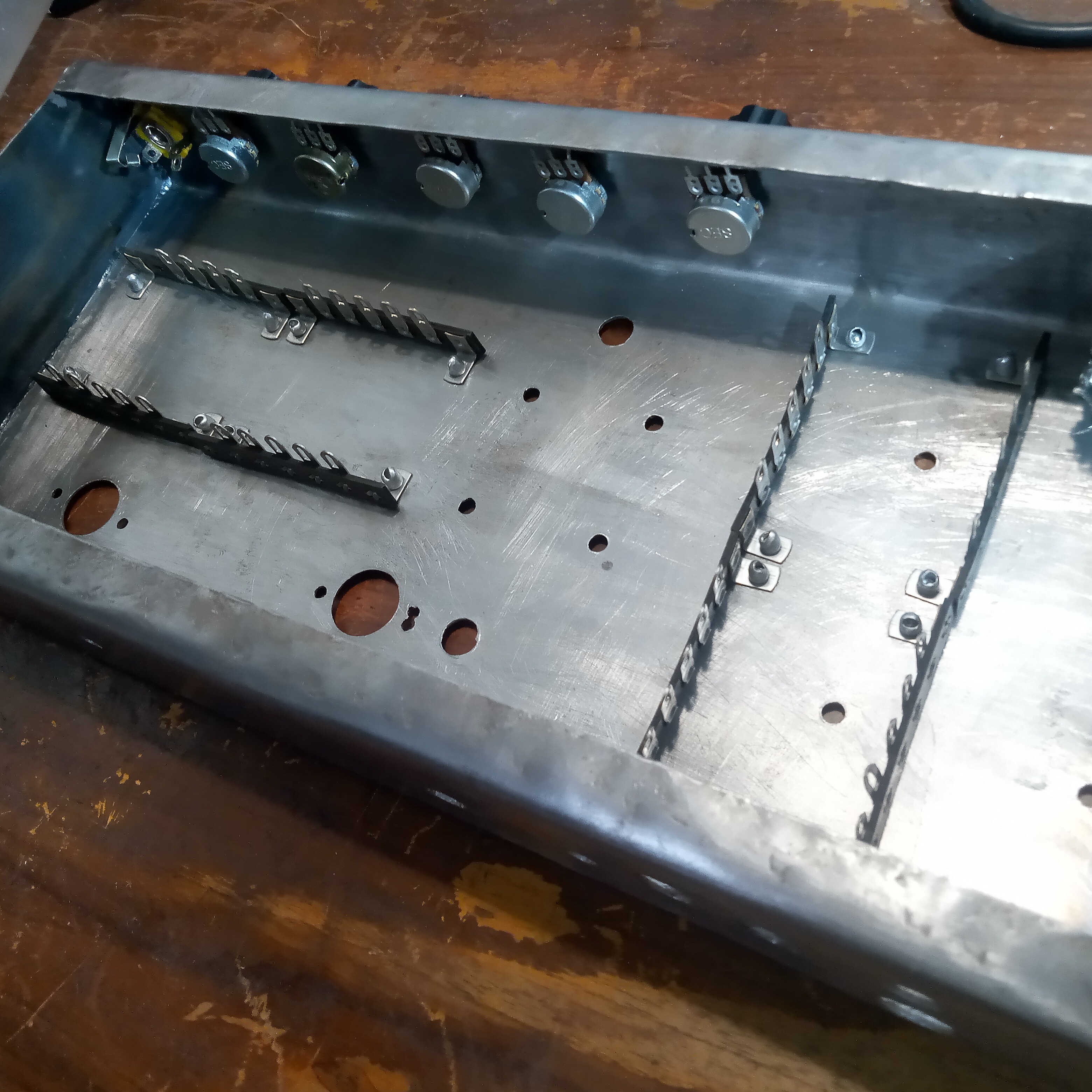
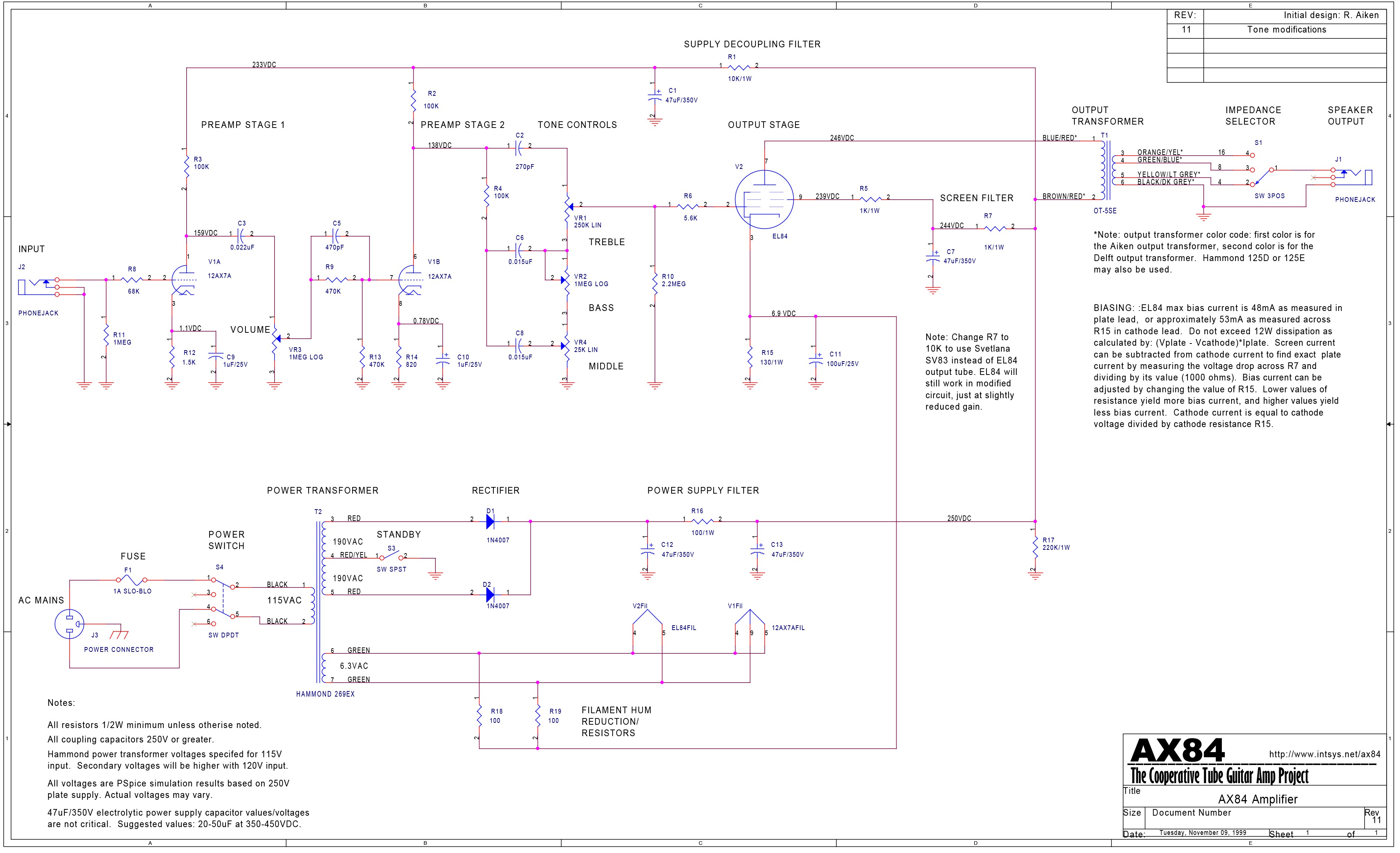
The amplifier was built in a custom chassis that I bent out of a piece of sheet-metal. I wanted to keep things as authentic as possible and avoid using a modern laser-cut or premade chassis. All the wiring is point-to-point on old-school terminal strips. The amplifier circuit is based on the "AX84" project, which takes inspiration from vintage Fender and Marshall guitar amplifiers from the 1950s and 1960s. New old stock made in India "BEL" tubes were used. The transformers were selvedged from a junked 1960s Phillips radio. I tried to analyse each stage of the circuit as I build the amplifier, to further my understand of vacuum tube circuits. Please check out the project logs below for more details. This was my first ever attempt at building a tube amplifier, so it is far from perfect. The goal of the project was education as opposed to building the best amplifier possible, however the amp sounds great and has very low background noise/hiss even compared to some commercially available modern vacuum tube guitar amplifiers. I would like to re-build it someday in a better chassis and clean up the wiring as well.

  • Part 5 – Point to Point Wiring and Testing

    _electroidiot11/19/2023 at 18:00 0 comments

    Being a vintage buff, I decided to construct the entire circuit using point-to-point wiring on tag-strips riveted onto the chassis. I followed a wiring diagram found online but made some changes to improve the grounding scheme. The layout is still not ideal but worked out well in the end. After building the 12AX7 preamp stages, I had some trouble with excess plate current. This turned out to be due to either faulty or mis-labelled valves, so the project was delayed until I could get another set from a different source. I tested each stage as I built the circuit, there were a few hiccups that had to be dealt with along the way, but in the end the amplifier works well and sounds great. For more details on each part of the build, please refer to my 4-part vlog videos on YouTube:

    Part 1, chassis fabrication and planning, power supply:

    Part 2, filament wiring and power supply updates:

    Part 3, wiring the amp stages and some problems with biasing:

    Part 4, some tweaks, checking gain and power output, final test:

  • Part 4 – Circuit Analysis

    _electroidiot11/19/2023 at 17:54 0 comments

    1st Preamp Stage

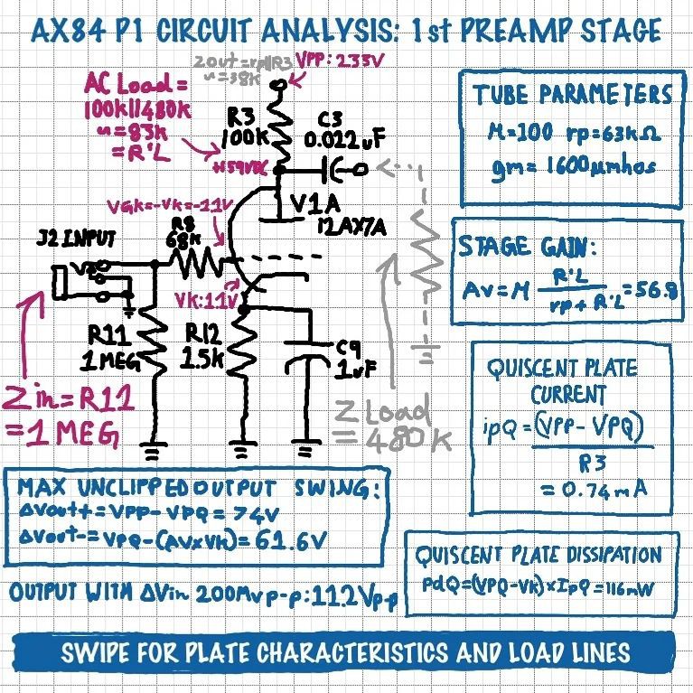
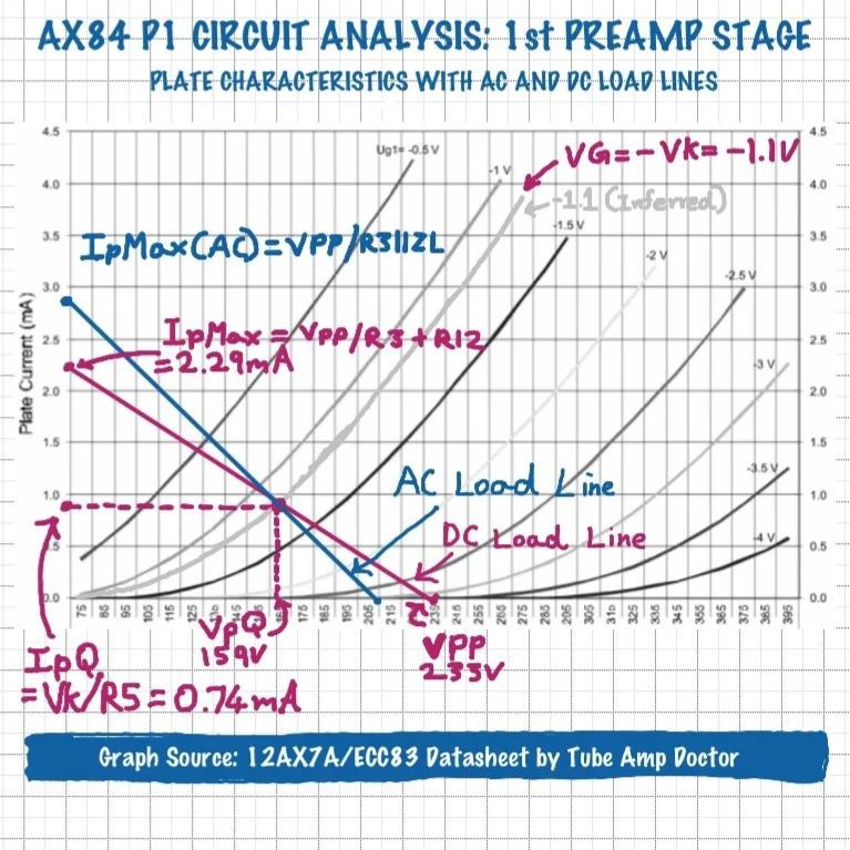
    The AX84 uses just two tubes, a 12AX7/ECC83 and an EL84. But since the former is a dual triode, there are three tube stages in total. Let's see what we can work out about the first half of the 12AX7, which serves as the input stage, using the component values and voltages given on the schematic.

    • Input Impedance – Since the grid doesn't draw any current, Zin = R11 = 1 Meg.

    • R8 is a grid leak resistor which forms a low pass filter with the parasitic capacitance of the grid, in order to prevent oscillation and RF interference.• Quiescent Plate Current – ipQ = (VPP-VPQ) / R3 = 0.74mA

    • Quiescent Plate Dissipation – pdQ = (VPQ-Vk) × ipQ = 116mW• Equivalent AC Load Resistance – R'L = R3 || Zload = 83K, where Zload is the approximate input impedance of the next stage.• Voltage Gain – Av = Mu × (R'L/rp+R'L) = 56.3. For reference, this would mean that ∆200mV at the Input would results in ∆11.2V at the output.

    • Maximum Positive Output Swing Before Clipping – ∆Vout+ = VPP - VPQ = 74V.

    • Maximum Negative Output Swing Before Clipping – ∆Vout- = VpQ - (Av × Vk) = 61.6V. This is because once the positive input swing overcomes the negative grid bias, the grid is driven positive causing soft clipping.• Output Impedance – Zout = rp || R3 ~= 38K.

    2nd Preamp Stage

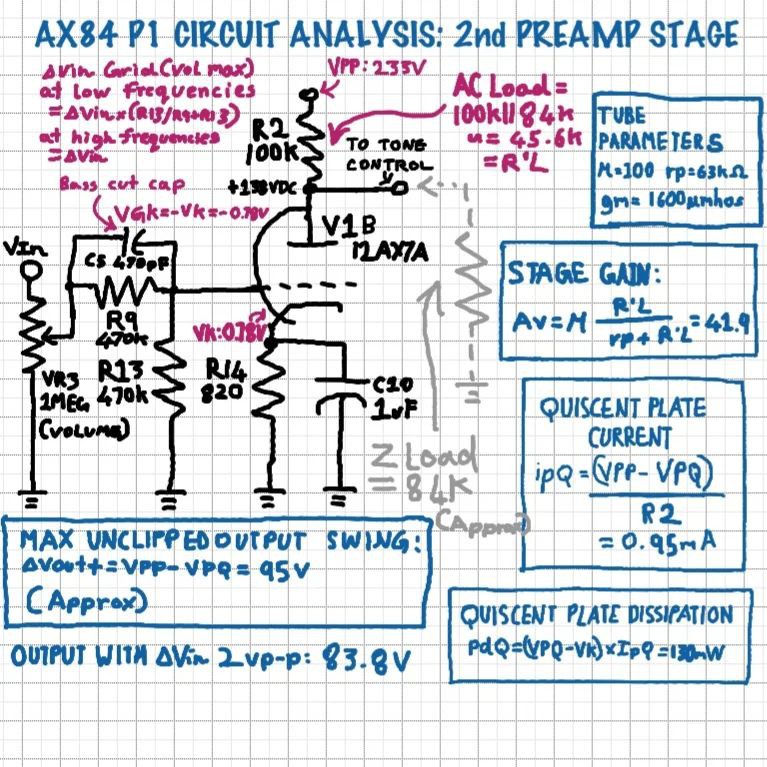
    The other half of the 12AX7is used as another common cathode gain stage, similar to the first. However, there are a few differences.

    • The output of the first stage is fed to a 1 Meg logarithmic pot for volume control.

    • C5 and R9 form a frequency dependent voltage divider along with grid resistor R13. This is done to attenuate low frequencies, thus C9 could be called a bass cut capacitor. Basically, C9 appears as a short to high frequencies, making the whole input available at the grid, but at lower frequencies it appears as an open, causing those frequencies to be attenuated by the R9 R13 voltage divider. If C9 and R13 are seen as a high pass filter, the 3dB point works out to be around 720Hz.

    • Input Impedance – The input impedance varies based on the position of the volume control and the signal frequency. When the volume is at maximum, and the frequency is High enough that C9 appears as a short, we can approximate Zin = R13 = 470K.

    • Quiescent Plate Current – ipQ = (VPP-VPQ) / R2 = 0.95 mA.• Quiescent Plate Dissipation – pdQ = (VPQ-Vk) × ipQ = 130mV.

    • Equivalent AC Load Resistance – R'L = R2 || Zload = 45.6, where Zload is the approximate input impedance of the tone stack. More on that in part 3!Voltage Gain – Av = Mu × (R'L/rp+R'L) = 41.9. For reference, this would mean that ∆2V at the grid would result in ∆83.8V at the output.• Maximum Positive Output Swing Before Clipping – ∆Vout+ = VPP - VPQ = 95V.

    • Maximum Negative Output Swing Before Clipping (approximate, since the plate curves get very non linear towards saturation) – ∆Vout- = VpQ - (Av × Vk) = 105V.• Output Impedance – Zout = rp || R2 ~= 38K.

    Tone Controls

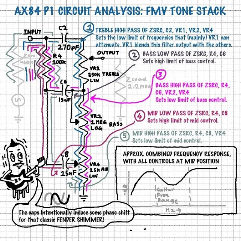
    The AX84 uses a variation of the classic FMV tone stack. This is a circuit that many people struggle with, but let's see if we can make sense of it.

    Essentially, the FMV stack is a combination of 5 filters that are all interdependent on each other. The filters output certain frequency ranges to the "stacked" treble, bass, and mid pots which are used to attenuate the various signal outputs as well as alter the response. The filters can be broken down as follows:

    • The high pass of Zsrc, C2, VR1, VR2, VR4 sets the low limit of the treble control. Treble pot VR1 blends the outputs of the treble filter and the bass and mid pots, feeding the signal to the next stage. Note that Zsrc is the preceding stage's output impedance. It is not strictly a part of the tone stack, but I have chosen to include it as it has a considerable effect on the filters' frequency responses.

    • The low pass of Zsrc, R4, C6 affects the high point of the bass filter's response. Interestingly, this point is out of the guitar's frequency range, so the "slope" of...

    Read more »

  • Part 3 – Power Supply

    _electroidiot11/19/2023 at 17:43 0 comments

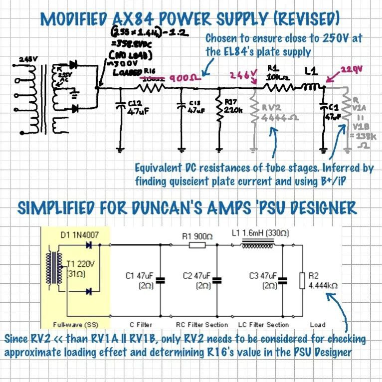
    The power supply section was built around a salvaged Philips radio power. transformer, as mentioned earlier. As my transformer had different secondary windings than the one recommended by the AX84 project, I had to make some changes to the circuit. I worked out the new value for the main voltage dropping resistor using a combination of IRL experimentation and Duncan's Amps' PSU designer.

  • Part 2 – Chassis Fabrication

    _electroidiot11/19/2023 at 17:35 0 comments

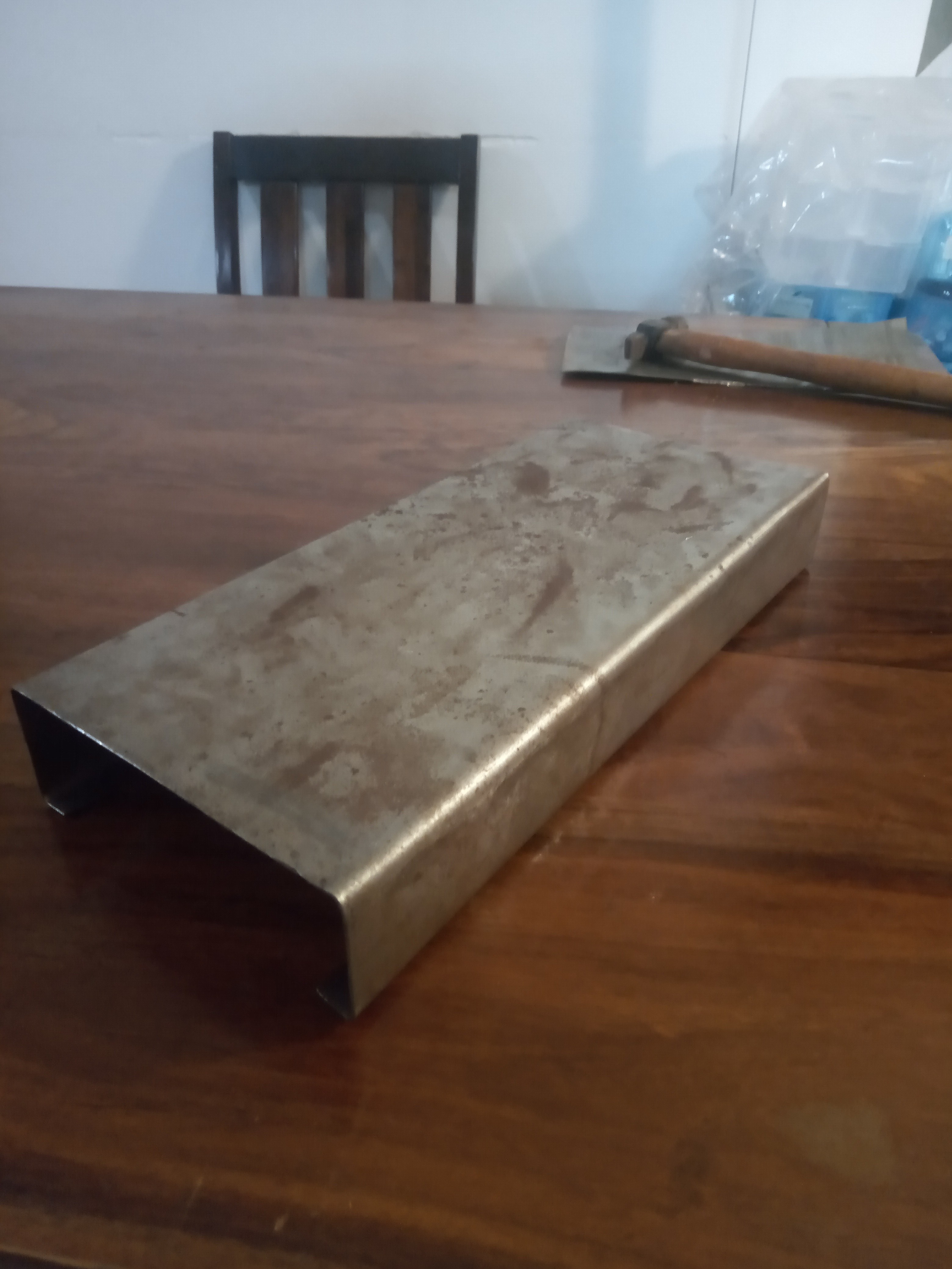
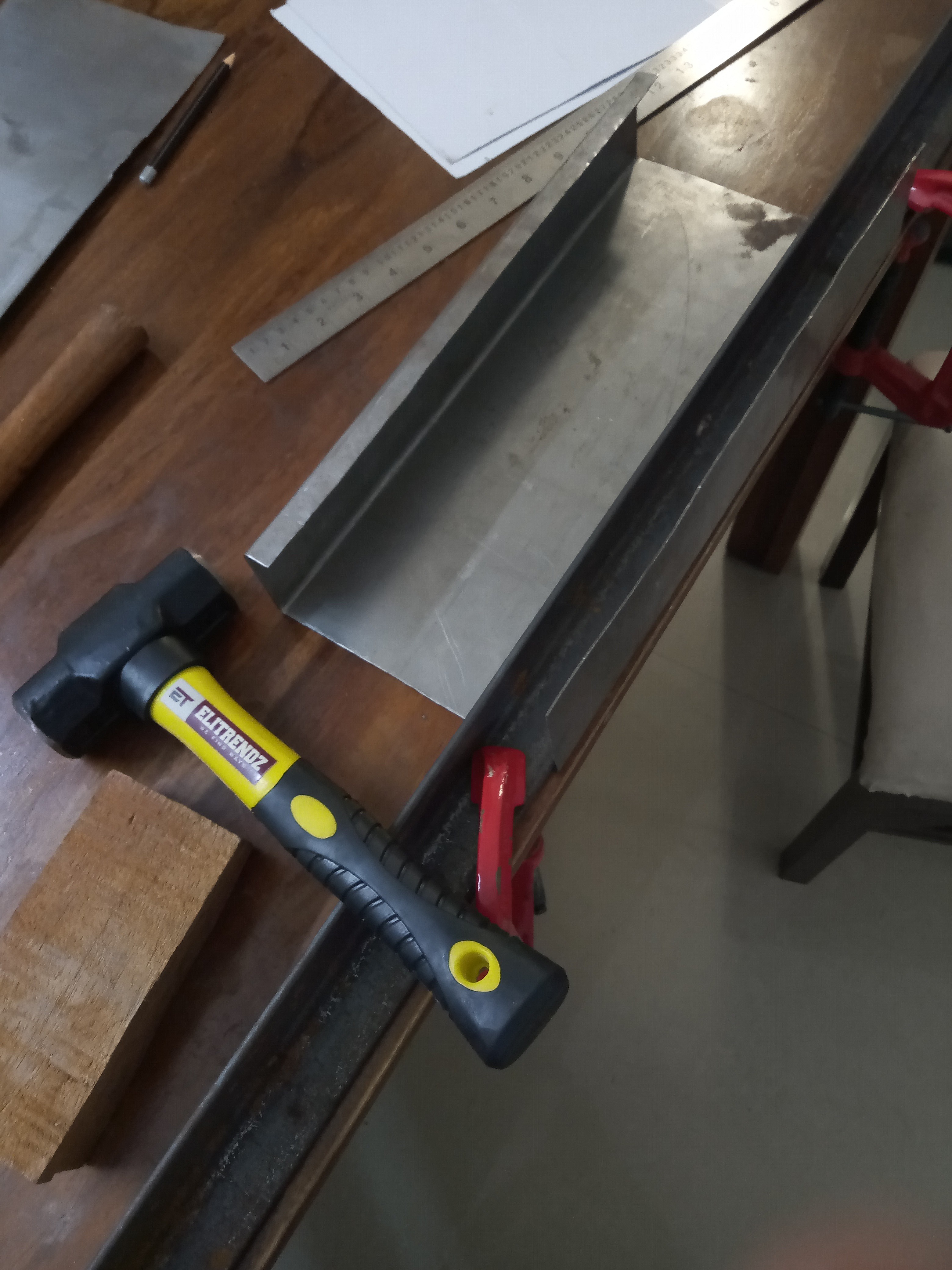
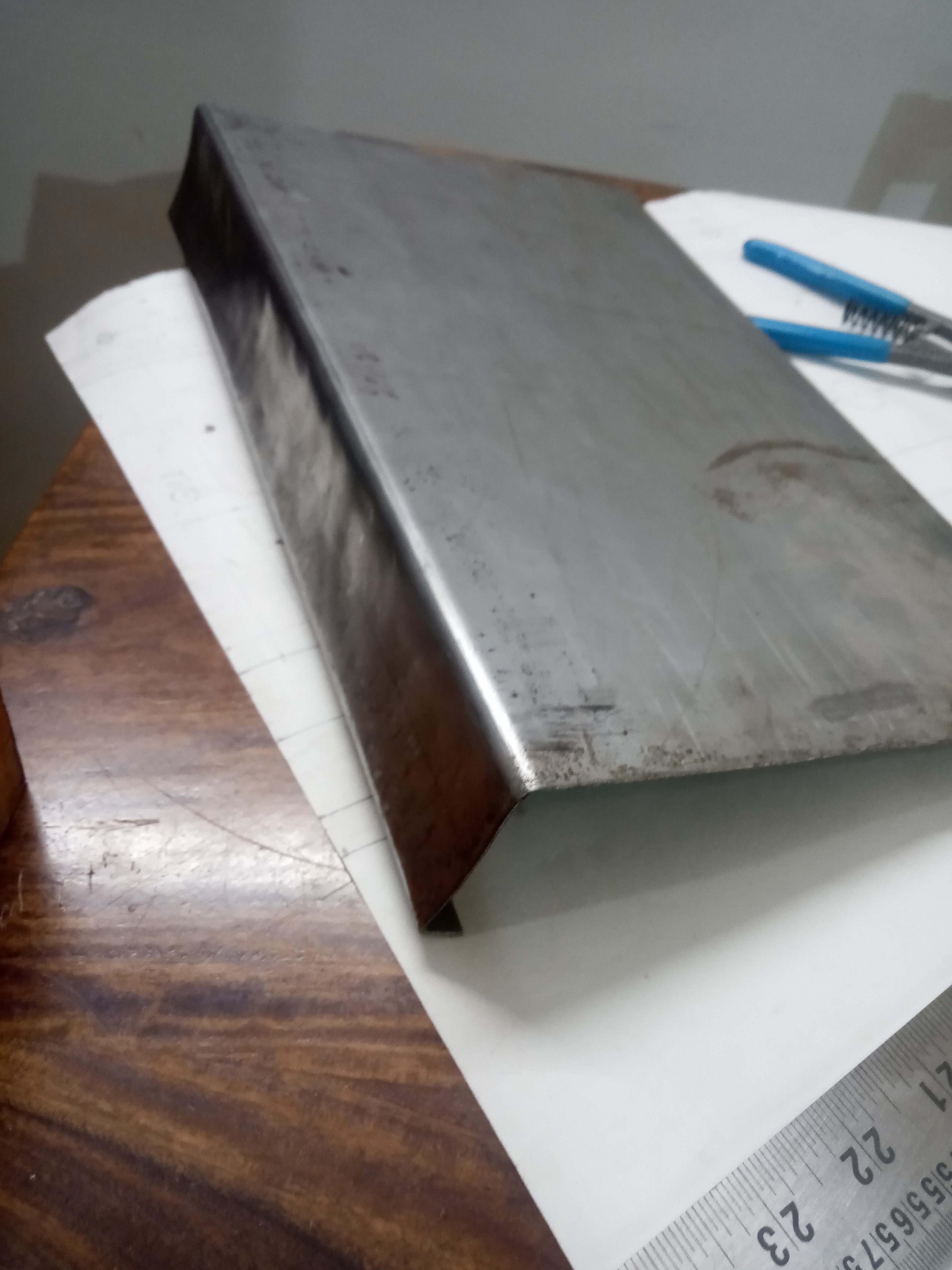
    I started with a sheet of 18-gauge sheet metal which in retrospect turned out to be too thick to work with easily. I bent the sheet and drilled the holes myself on the kitchen table, but I enlisted the help of an auto body repair place for cutting the sheet metal and welding the sides. The end result is far from perfect, but I have decided to embrace the rustic steam punk aesthetic by clear coating it instead of trying to hide the flaws with paint.

  • Part 1 – Introduction

    _electroidiot11/19/2023 at 17:32 0 comments

    Building a tube amp has been a dream of mine for a couple of years. in 2022, I was finally able to start my build which is now complete. I was on a tight budget, and my main goal was to learn about tube/valve amp construction through this build, and not necessarily build the best possible amplifier. Thus I decided on the AX84 guitar amp circuit found online, more details are available here: http://ax84.rru.com/Basically, it consists of two preamp stages using one 12AX7/ECC83 and a single-ended output stage using an EL84. These being common valves made by BEL (Bharat Electronics Limited, the Indian state-owned electronics company that used to make valves locally) is another reason that I decided to go with this circuit. It is based on the vintage tube guitar amps of the '50 and '60s by Fender, Marshall, etc... To keep costs down, I purchased a junk, non-restorable 1960s Philips radio for parts. The entire body was missing, but I was able to use the power transformer and output transformer for my build. 

View all 5 project logs

Enjoy this project?

Share

Discussions

Johan Carlsson wrote 11/29/2023 at 18:30 point

Looks great, sounds great! Thanks for documenting the design and build so well!

  Are you sure? yes | no

Dan Maloney wrote 11/20/2023 at 19:42 point

Sounds good, looks good! Love that cordwood construction. Nice job!

  Are you sure? yes | no

Similar Projects

Does this project spark your interest?

Become a member to follow this project and never miss any updates