Overview
As mentioned in my last log, I had an issue where I “needed” to explain why a current mirror wasn’t working as expected. I thought I had helped solve a colleague’s issue, but it turned out to a be red herring… now their current mirror was using Onsemi FMBA06 (for those playing along at home) and still performing terribly.
Two birds one stone. I decided I’d try to root cause the issue and learn lab automation at the same time. I knew my equipment could be programmed but wasn’t sure how. Luckily, I quickly found PyVisa1, and spun up a BJT Plotter2 over a weekend.
Note 1 - If you have some new-ish lab equipment likely supports SCPI… I strongly recommend you give this python package a try. Its freaking phenomenal!
Note 2 – Yes, I’m aware you could accomplish similar results with a function generator and an oscilloscope in XY mode… let me cook!
Setup
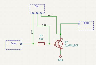
The test setup is shown below… I should REALLY replace my Oscilloscope with a bench DMM (insert “if I had one meme”). The function generator is used as a DC supply capable of 1mV steps. I have to use a fairly large base resistor to squeeze out any accuracy I can from my scope. The scope then measures the current into the base, as well as the voltage Vce, swept by the PSU.

Scripting - Set Ib & Sweep VCE
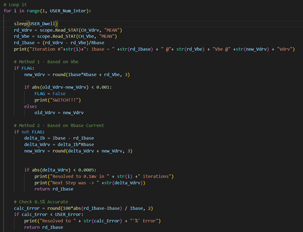
The script should be as easy as (1) set Ib, then (2) sweep Vce? And yup it’s that easy. Shown below is the main for loop of the BJT Plotter script.

To set the base current I use the Set_Ibase function shown below. It first assumes Vdrv = Ib*Rb-Vbe, then it sets the function generator to output Vdrv, and measures the true Vbe. Vdrv can then be recalculated, and the process can be repeated. I found that this method quickly converged to its final value, but since Vbe is so small it’s difficult to converge to the CORRECT value.
The second method is to assume Vbe is constant, and then focus on the desired change in base current. This way we’re not dealing with tiny changes in voltages (below 1mV in the case of Vbe), and I can focus on the somewhat large voltage across Rbase.

Here’s an example of the 2-stage algorithm working. Notice that iteration 2 and 3 measured IDENTICAL Vbe. I need a much more accurate/precise instruments to use method 1 by itself.

Final Result
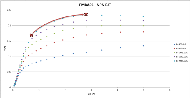
Sweeping the part revealed the following curves… Gross! At higher currents the knee of the saturation region stretches out much further than I expected. We can imagine the two transistors in the current mirror as the X’s on the 500uA curve. The left X would be the load setting BJT, and the right X would be the sinking/sourcing BJT. The left X is locked to Vbe(on), but the right X will see Vce varied with load. Clearly this current mirror won’t work great, and it doesn’t!

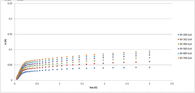
A quick sanity showing the BJT plotter on a well-documented part (2n3904). Curves look good!

TLDR - Onsemi FMBA06 makes for a poor current mirror at my operating point.
 Jesse Farrell
Discussions
Become a Hackaday.io Member
Create an account to leave a comment. Already have an account? Log In.