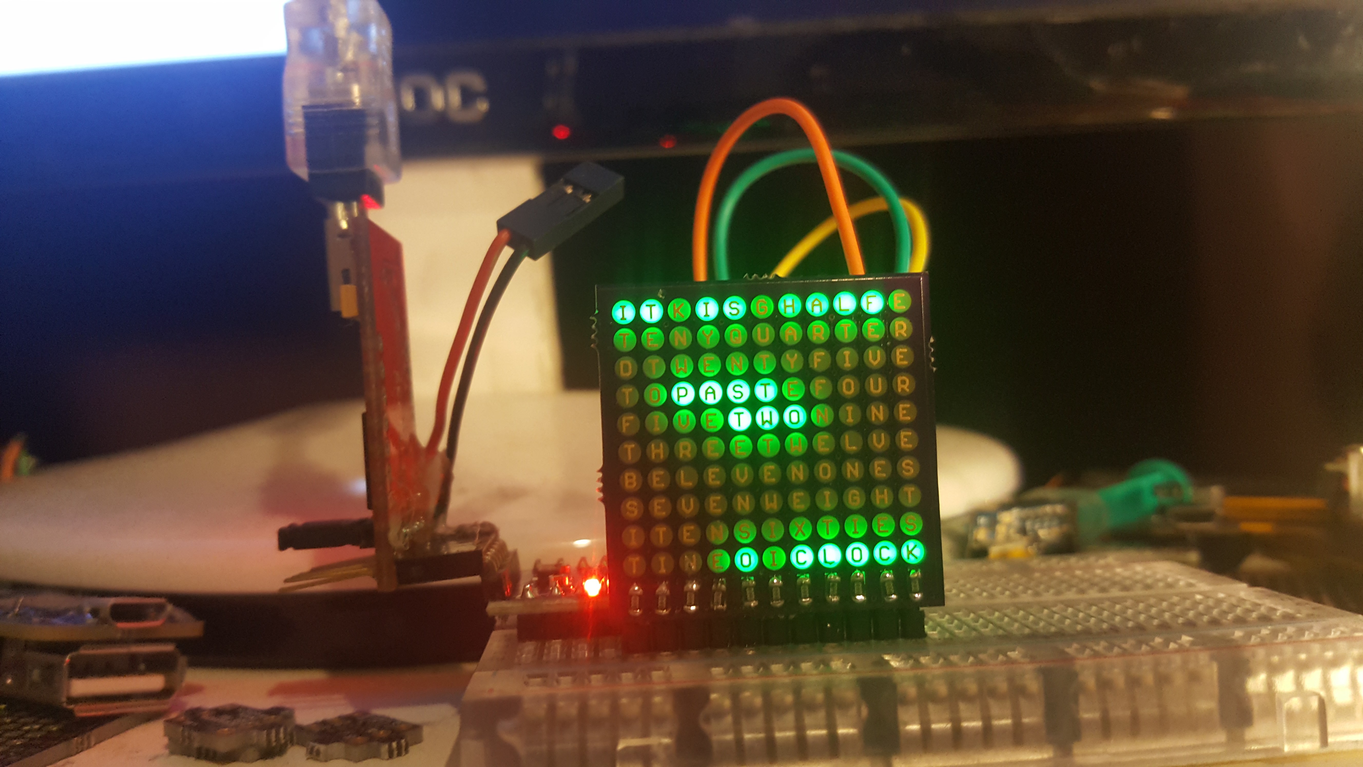
Update fun fact: analyzing a charlie plexed matrix for bugs is so much easier when the LEDs are upside down - because of the markings :)
I finally got my LEDs and took the time to hand solder a PCB :) it bleeds a bit in the picture, but in real life it's quite good. The code so far is only a mock up, but there is scanning and matrix stuff involved already.

#include <avr/pgmspace.h>

const int leds[]  = {2,3,4,5,6,7,8,9,10,11,12,13};

const int matrix[10][11][2]  = {
  {  {1, 0},  {0, 1},  {0, 2},  {0, 3},  {0, 4},  {0, 5},  {0, 6},  {0, 7},  {0, 8},  {0, 9}, {0, 10} }, // 0
  {  {2, 0},  {2, 1},  {1, 2},  {1, 3},  {1, 4},  {1, 5},  {1, 6},  {1, 7},  {1, 8},  {1, 9}, {1, 10} }, // 1
  {  {3, 0},  {3, 1},  {3, 2},  {2, 3},  {2, 4},  {2, 5},  {2, 6},  {2, 7},  {2, 8},  {2, 9}, {2, 10} }, // 2
  {  {4, 0},  {4, 1},  {4, 2},  {4, 3},  {3, 4},  {3, 5},  {3, 6},  {3, 7},  {3, 8},  {3, 9}, {3, 10} }, // 3
  {  {5, 0},  {5, 1},  {5, 2},  {5, 3},  {5, 4},  {4, 5},  {4, 6},  {4, 7},  {4, 8},  {4, 9}, {4, 10} }, // 4
  {  {6, 0},  {6, 1},  {6, 2},  {6, 3},  {6, 4},  {6, 5},  {5, 6},  {5, 7},  {5, 8},  {5, 9}, {5, 10} }, // 5
  {  {7, 0},  {7, 1},  {7, 2},  {7, 3},  {7, 4},  {7, 5},  {7, 6},  {6, 7},  {6, 8},  {6, 9}, {6, 10} }, // 6
  {  {8, 0},  {8, 1},  {8, 2},  {8, 3},  {8, 4},  {8, 5},  {8, 6},  {8, 7},  {7, 8},  {7, 9}, {7, 10} }, // 7
  {  {9, 0},  {9, 1},  {9, 2},  {9, 3},  {9, 4},  {9, 5},  {9, 6},  {9, 7},  {9, 8},  {8, 9}, {8, 10} }, // 8
  { {10, 0}, {10, 1}, {10, 2}, {10, 3}, {10, 4}, {10, 5}, {10, 6}, {10, 7}, {10, 8}, {10, 9}, {9, 10} } // 9
};

const boolean img [10][11] = {
  { true,  true, false,  true,  true, false,  true,  true,  true,  true, false},
  {false, false, false, false, false, false, false, false, false, false, false},
  {false, false, false, false, false, false, false, false, false, false, false},
  {false, false,  true,  true,  true,  true, false, false, false, false, false},
  {false, false, false, false,  true,  true,  true, false, false, false, false},
  {false, false, false, false, false, false, false, false, false, false, false},
  {false, false, false, false, false, false, false, false, false, false, false},
  {false, false, false, false, false, false, false, false, false, false, false},
  {false, false, false, false, false, false, false, false, false, false, false},
  {false, false, false, false,  true, false,  true,  true,  true,  true,  true},
};

void setup()  { }

void loop() {
    for (int y=0; y<10; y++)
    {
      for (int x=0; x<11; x++)
      {
        if (img[y][x]) charlie_matrix (x, y);
    }
  }
}

void charlie_matrix (int x, int y)
{
   int cx = matrix[y][x][0];
   int cy = matrix[y][x][1];

  digitalWrite(leds[cx], LOW);
  pinMode(leds[cx], OUTPUT);
  digitalWrite(leds[cy], HIGH);
  pinMode(leds[cy], OUTPUT);
  delayMicroseconds(65);

  pinMode(leds[cx], INPUT);
  digitalWrite(leds[cx], LOW);
  pinMode(leds[cy], INPUT);
  digitalWrite(leds[cy], LOW);

  delayMicroseconds(5);
} davedarko
Discussions
Become a Hackaday.io Member
Create an account to leave a comment. Already have an account? Log In.
A green filter might improve contrast. If you want I can send you a few pieces of the several shades of green filters I have large rolls of. One of them is sure to work.
Are you sure? yes | no
ouh, for the sake of science, why not? :)
Are you sure? yes | no
Very nice!
Are you sure? yes | no
awesome!
Are you sure? yes | no
Lookin' Good! Occurs to me, if bleed is a concern, one method might be to insert a few vias between.
Are you sure? yes | no
hm, but if I put vias between, then I have to widen the space between LEDs, which also works against bleeding, but might work against readability :) I still have a thinner(0.8mm) german version to solder - for another day, because I hand solder them and it took a while... but was great on the same time, very relaxing ;)
Are you sure? yes | no
Pros and cons! I don't mind the "bleeding", was just pleased with myself that I came up with a way to limit it while still being PCB-able :) Also, "the bleed" (depending on how much it's visible in real-life vs a photo) could be used to advantage, in an artistic-sense. A very cool experiment, with great results, and plausibly useful in entirely different designs, as well.
Are you sure? yes | no