Schematics
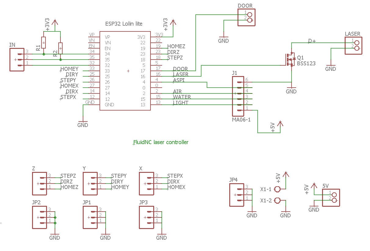
My new control board will look too much simple compared to the old one.
Based on an ESP32 it cannot be more simple!

Schematic is self explainatory. This board is mainly an IO board allowing:
- to control 3 stepper motors (see later)
- to detect 3 independant home switches
- to apply PWM to the laser controller (see later)
- to detect interlock door switches
- to drive 4 220V relays for air assist, vacuum pump, water cooling and light
- to read 3 more inputs
All the power of this board is in its firmware. I will use the excellent FluidNC solution
PCB
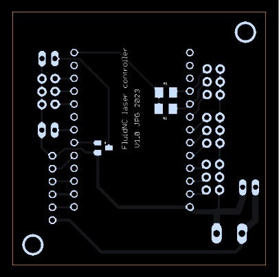
PCB was easy to route! It is available on PCBWay shared projects:
https://www.pcbway.com/project/shareproject/FluidNC_laser_controller_board_70101fd4.html

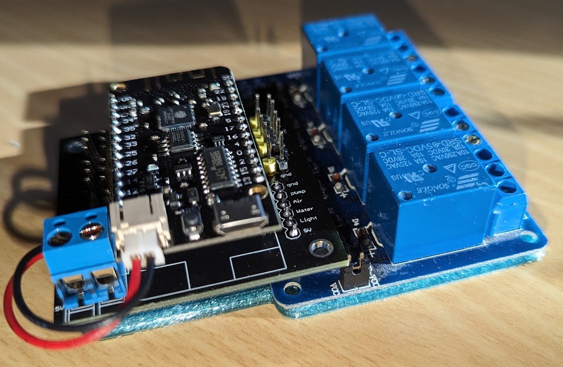
PCBWay kindly sponsored this project. The board once solder is compact (5x5 cm) on which you have to add the relays board.

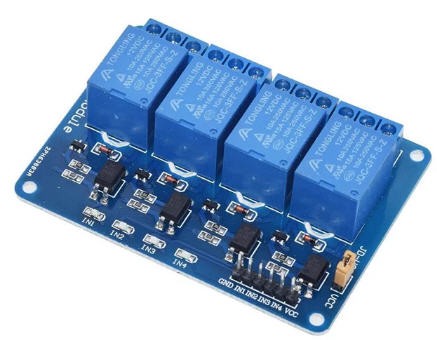
This board uses optocouplers on the input stage. It is particularly safe to control 220V loads. I power it with 5V but can control the inputs with 3.3V IOs coming from the ESP32.
Once soldered the board remains very compact and can be fixed using this 3D printed support.

 JP Gleyzes
Discussions
Become a Hackaday.io Member
Create an account to leave a comment. Already have an account? Log In.