 Steph
StephTurn on the Light
[Chorus]
Bend me, shape me, any way you want me
Long as you love me, it's all right
Bend me, shape me, any way you want me
You got the power to turn on the light
-from the song "Bend Me Shape Me" by The Outsiders, 1966
The push-on/hold-off functionality of this circuit is provided by the magic of MOSFETS. A MOSFET is just a type of transistor, which we use to control the flow of electrons between the battery and the rest of the circuit.
Specifically, we use two MOSFETS to form a latch. In this configuration, the first MOSFET is activated by a switch, which momentarily turns on the circuit. This power activates the second MOSFET, which then performs the same function as the switch: holding the first MOSFET on. This means that one short push of a momentary contact button will hold the circuit on indefinitely. More about the specifics later.
I (slightly) modified a latch circuit published here by Mosaic Industries:
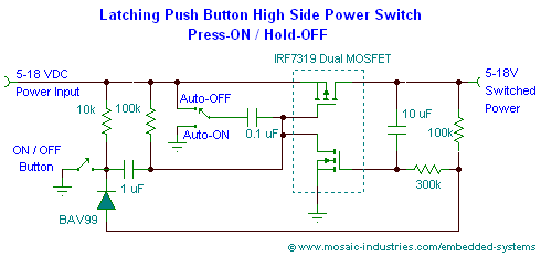
This circuit has one additional feature which is both a neat trick and also critical for our device to function: the button used for the main power switch can also be used to control other things once the circuit is on. This allows the use of a single button for both power and control.
I replaced the dual MOSFET used in the original circuit with the SIA517DJ, which i chose for a few reasons:
- It's available in a tiny 2mm x 2mm SC-70 footprint.
- It runs on voltages down to 1.5v
- My supplier had them in stock
It also has an on-resistance of a scant 0.17 ohms, so it wastes very little energy while doing its job. It also has a maximum reverse-leakage of just 1μA, meaning our battery will only drain a tiny bit while the menorah is off.
Won't you P my neighbor?

Let's take a closer look at the dual MOSFET latching mechanism. There are two types of MOSFETs, P-channel and N-channel. Both types have the same three connections to the circuit:
- Source
- Drain
- Gate
Basically, in either type the gate controls the flow of electrons between the source and drain.
The difference between N and P types?
A P-channel MOSFET turns on when its gate is low, while an N-channel MOSFET turns on when its gate is high. Our SIA517DJ dual MOSFET packages both types together, because they are often used together in a complementary fashion (see: CMOS).
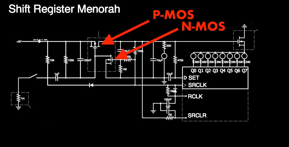
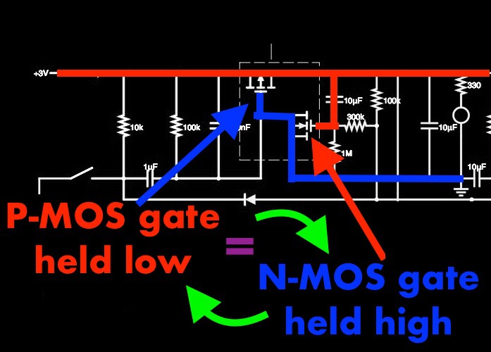
In our circuit, we use the P-MOS as the main power control switch, while the N-MOS simply serves to hold the P-MOS gate low, keeping the circuit latched on. Here's how it works:
STEP 1:
In our circuit, as soon as power is applied, the gate of the P-MOS is brought high. This starts the P-MOS in the off-state, meaning no power flows to the rest of the circuit. However, this gate is also connected to ground through our switch:
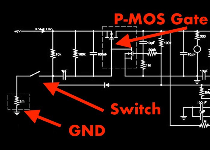
Pressing the switch brings the gate low rapidly, and since a P-MOS turns on when its gate voltage is low, this instantly activates the P-MOS. Because our battery is connected at the source of the P-MOS, it will now flow through the P-MOS and into the rest of the circuit.
STEP 2:
As soon as that power starts to flow through the P-MOS, voltage at the N-MOS gate starts to rise. Here is the path it takes:
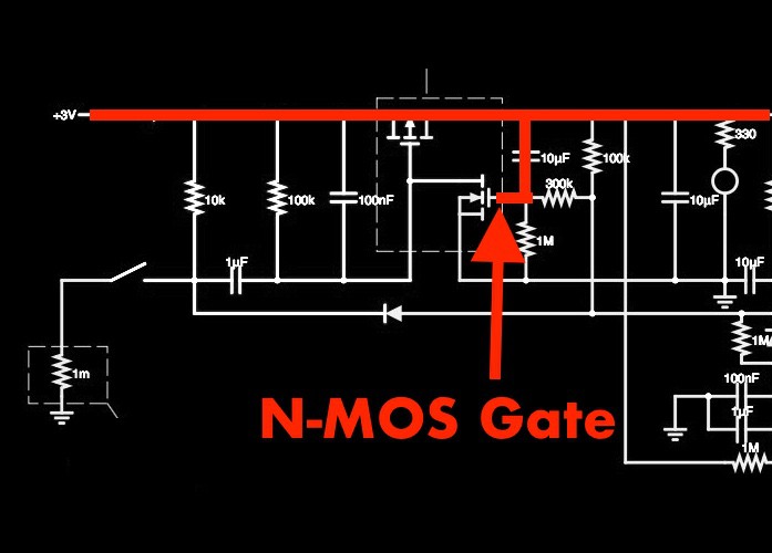
Since an N-MOS activates with positive voltage, it now allows current to begin flowing. The N-MOS source is actually connected to ground, and its drain is connected to the P-MOS gate. As a result, any charge on the P-MOS gate will drain away to ground. Now, the P-MOS will stay on permanently, even when the switch is released.
Now, the circuit will stay on, with the MOSFETs holding each other open, until the cycle is somehow broken. Which brings us to...
STEP 3
Our button is also connected to the N-MOS gate through a large resistor and a diode, which allows the gate to be drained slowly if the switch is held down. Holding the button discharges the capacitor through the resistor via the blue path:
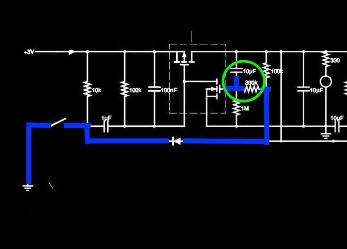
This combination of a 10µF capacitor draining through a 300kΩ resistor takes 3-5 seconds to lower the voltage at the N-MOS gate, from a starting voltage of 3v to its off-voltage of approximately 1v, at which point the N-MOS will turn off. In turn, this disconnects the P-MOS gate from ground, allowing its voltage to rise past the P-MOS gate's threshold voltage of approximately 1v. Now, the P-MOS will stop conducting, and the circuit will be disconnected from the battery again, and remain in the off state.
It will stay that way until the button is pressed again, discharging the P-MOS gate to ground and starting the cycle over again.
Discussions
Become a Hackaday.io Member
Create an account to leave a comment. Already have an account? Log In.