 Michael Gardi
... having an actual physical object to model from is a joy.
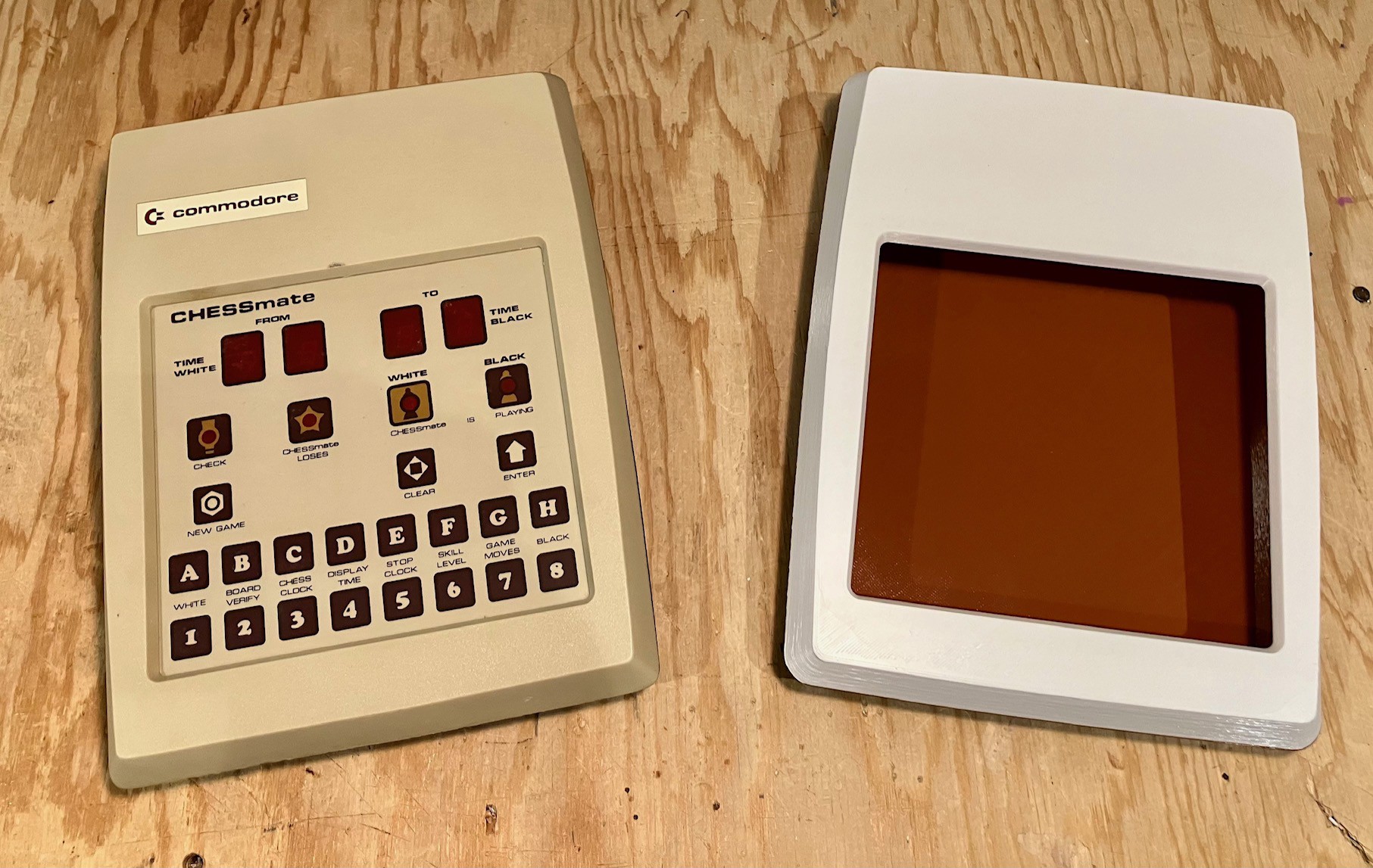
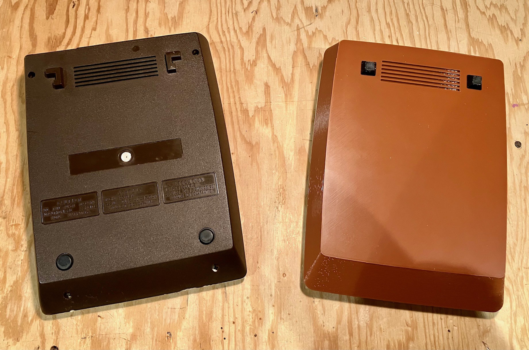
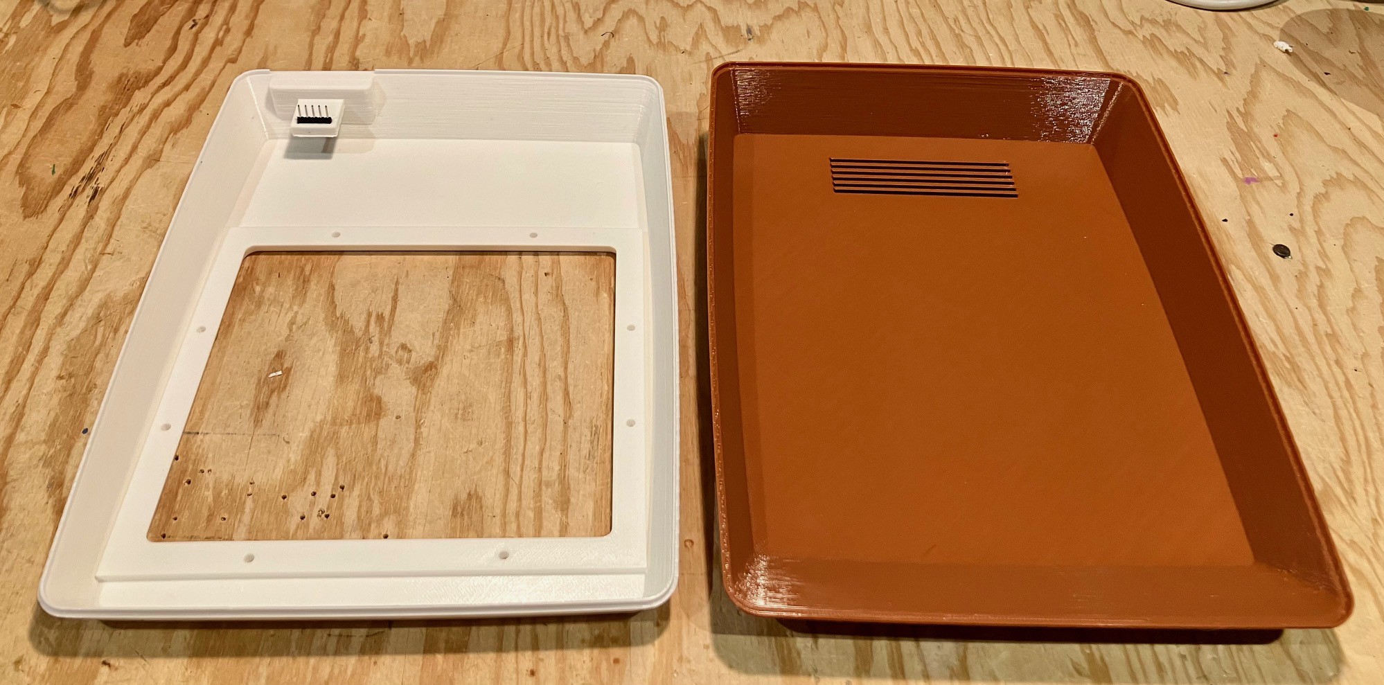
I'm going to have to work on the colors, but I'm pretty happy with my first crack at the CHESSmate case.
I've simplified the model somewhat. I may go back in to add some cosmetic details later.
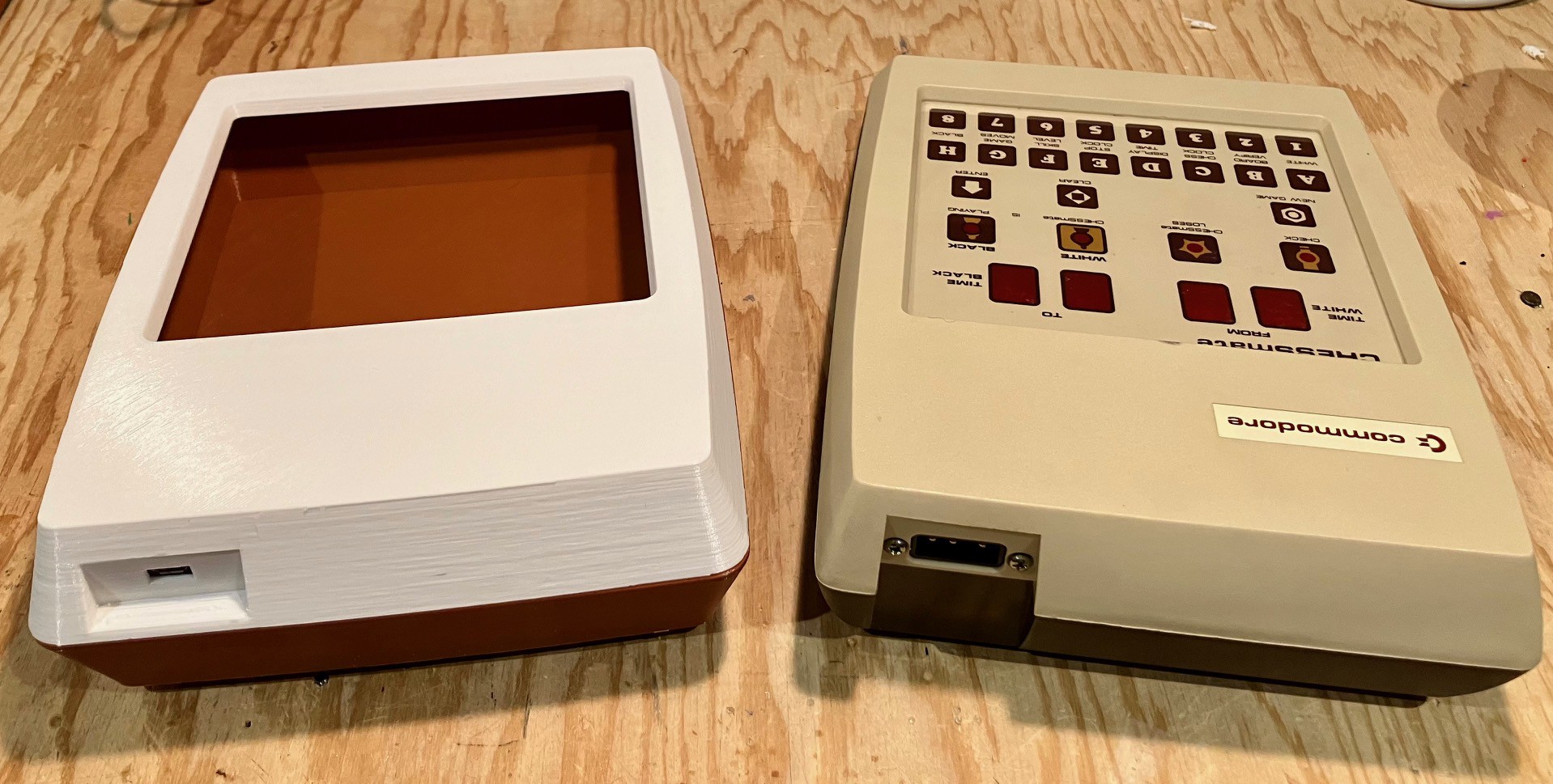
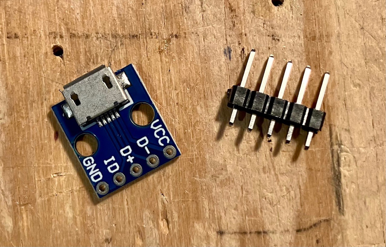
I did make one outward change, to the power connector, opting for a more modern micro USB connector (because I had some of these lying around).
From the inside I modelled a "shelf" to hold the power connector. While I still like the idea, it turns out that once you have soldered the header to the PCB, it's pretty much impossible to insert the combined unit onto the shelf, not to mention the pain of removing support material that is required to print the shelf. I'll rework that in the next version.
On the inside I have removed all of the "posts" that were used to hold the CHESSmate PCB in place and to attach the top and bottom case pieces together. I have other plans for doing he same.

Discussions
Become a Hackaday.io Member
Create an account to leave a comment. Already have an account? Log In.
I don’t think I posted the schematic. You can find it here. http://retro.hansotten.nl/wp-content/uploads/2022/03/chessmate_schematic.jpg The 10V supply is regulated down to 5V for most everything, but is also run directly to the 7-segment displays (marked as “unstab” in the schematic). As I was unsure what was going on there I opted for the transformer.
Are you sure? yes | no
Ah a centre tap full wave rectifier. You can work it out from calculations. The peak value of 10 VAC rectified is about 14 VDC but in practice it'll be more like 12-13 VDC after various drops. So it'll work just fine with a 12 VDC supply wired to one of the diodes giving about 11.3 VDC. The unstab voltage only affects slightly the brightness of the display so isn't critical. The rest of the circuit runs off 5V.
Are you sure? yes | no
Thank you Ken for the explanation. My background is in software. I’m actually pretty weak on the electronics side and I was afraid of damaging this rare artifact.
Are you sure? yes | no
To be on the safe side you can measure the unstab voltage to see if it's as I predicted. Feeding it a lower voltage is in fact safer and will just result in slightly dimmer display. In any case 10 VAC is a nominal value and is expected to vary depending on the mains voltage it encounters.
Are you sure? yes | no
As an interim measure since the device has a rectifier and a regulator on board you could power it with a 12V universal wall wart recycled from an external HD or something power supply instead of bothering with the mains step up transformer.
Are you sure? yes | no
I would like to suggest a power supply connection/design improvement. The 3 pin plug is 10V AC. On the circuit board it is rectified and regualted to 5V. If you decide to clone the ciruit board, eliminate this circuitry. If you use a "wall wart" 5V supply used to charge a cellphone, you can feed it directly to the board 5V rail. Pick an input connector that matches your charger connector.
Are you sure? yes | no