Unfortunately the hardware parts aren't ready yet, as i hoped during my last post. So there is time to investigate the state machine, which will drive the barn door.
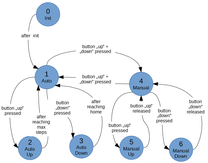
There are seven states which describe the planned functions. These states are shown in the following picture.

State 0 represents the initialisation step. Here the inputs and outputs will be configured, the barn door will be homed to its starting position and the button interrupts are attached. Thats basically what's done during the setup() routine. Afterwards it will change to the next state and enter the loop().
State 1 means that the barn door is idle and in automatic mode. The state only changes, when one or both buttons are pressed. Pressing the "up" button will change it to state 2, if there are steps left which will manipulate the upper arm. Pressing the "down" button will change it to state 3, if the arm isnt in home position. Pressing both "up" and "down" buttons at once will switch to state 4.
State 2 will be the main mode, where the stepper will move the upper arm to even out the earths rotation. After a maximal number of steps is reached, the upper arm will be fully errected and the stepper will stop. The programm will go back to state 1.
State 3 moves the upper arm back to its home position, as it will rotate backwards until a end stop signals that the arm has reached its home position. Afterwards it will change the state back to 1.
State 4 represents the manual mode. Pressing both "up" and "down" buttons at once will switch to state 1. Other than in state 1, the buttons need to be hold to move the upper handle. While button "up" is hold, the state 5 will move the handle up. When button "down" is pressed, stet 6 will move the handle down.
State 5 will move the handle upwards. The speed will increase while to button is pressed. After the button is released, it will change back to state 4. It will also change to state 4, when the end of the rod is reached.
Step 6 works as step 6, turning the stepper in the opposing direction. This will move the arm down, while the button is pressed or until the home position is reached.
Im not sure, if its required to insert a pause function in state 2.
Here you can see my first draft idea of how the state machine should work. I will post the final code, when its working :-)
boolean changed = false;
int state = 0;

void setup() {
  //configute inputs
  //configure outputs
  //home the arm
  attachInterrupts();
  state = 1;
}

void loop() {
	if(changed){
	//debounce delay
	//read buttons
	//change state
	changed = false;
	attachInterrupts(); //depending on state
	}
	switch case state:
		//Auto Idle
		case 1:
			while(!changed){
				//wait
			}
			break;
		//Auto up = tracking
		case 2:
                        if(maxSteps - actStep > 0){
			    deattachInterrputs();
			    //do the tracking
			    attachInterrupts();
}                       }
			break;
		//auto down = homing
		case 3:
                        if(endSwitch == false){
			    deattachInterrputs();
			    //home the arm
			    attachInterrupts();
                        }
                        break;
		//Manual idle
		case 4:
			while(!changed){
				//wait
			}
			break;
		//Manual up
		case 5:
			while(!changed && maxSteps - actStep > 0){
				//Move up
			}
			break;
		//Manual down
		//Also test for end switch, as the stepper can loose some steps
		case 5:
			while(!changed && actStep > 0 || endswitch == false){
				//Move down
			}
			break;
}

void buttonInterrupt(){
  changed = true;
  deattachInterrputs();
}
First i thought, that it would be a good idea to change the states during buttonInterrupt(). Unfortunately it's hard to recognize the double button press, as you can't and shouldn't use delay() in an ISR.
 MughtyWinky
Discussions
Become a Hackaday.io Member
Create an account to leave a comment. Already have an account? Log In.