 Ricardo Sappia
What´s inside?
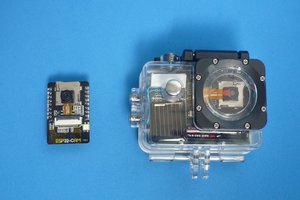
Here below you can find some more details about the required components needed for this project.
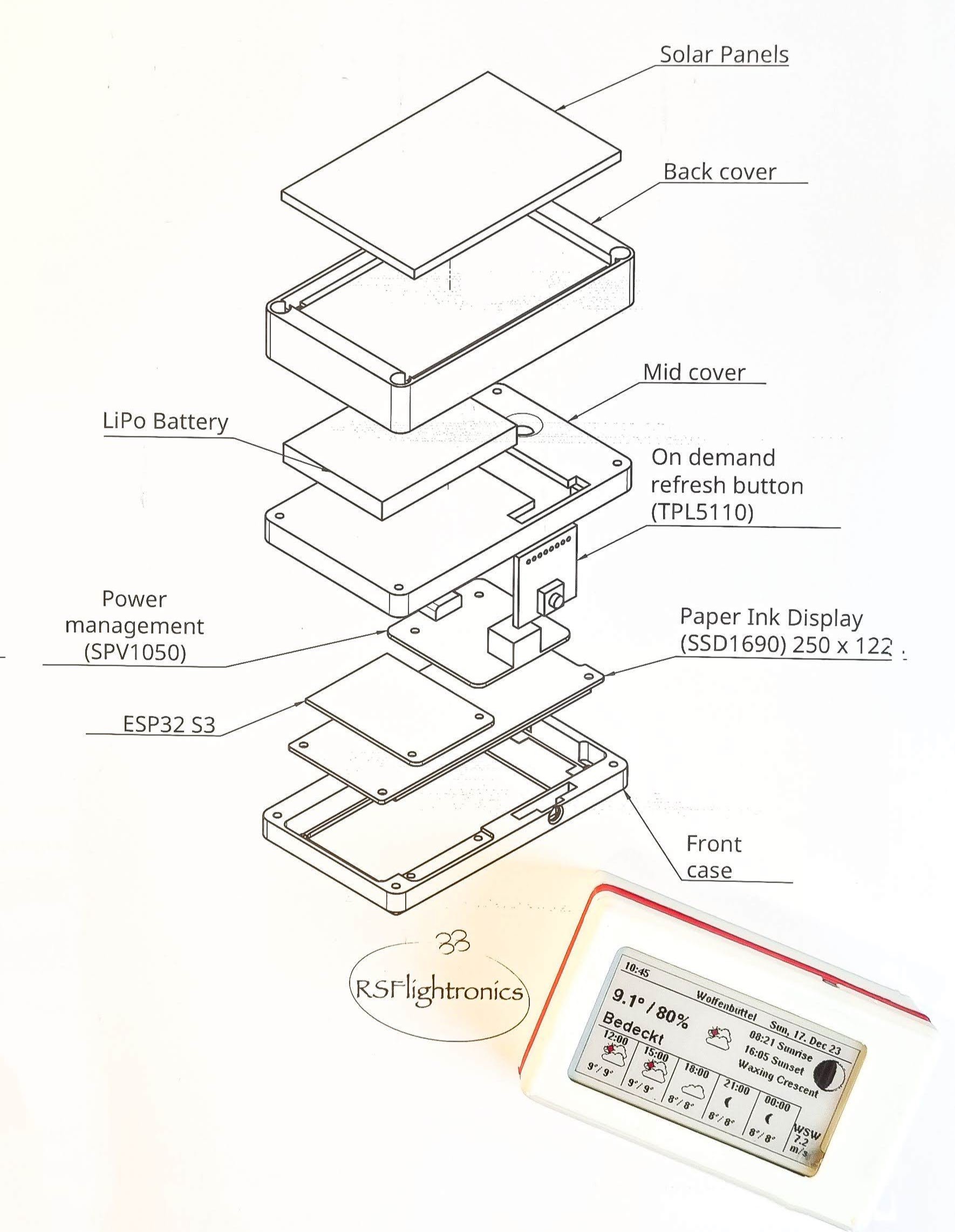
To have all the modules allocated into a small form factor I designed the chassis to be split into three parts. This allows to connect all modules while in place and makes the build process easier and cleaner.
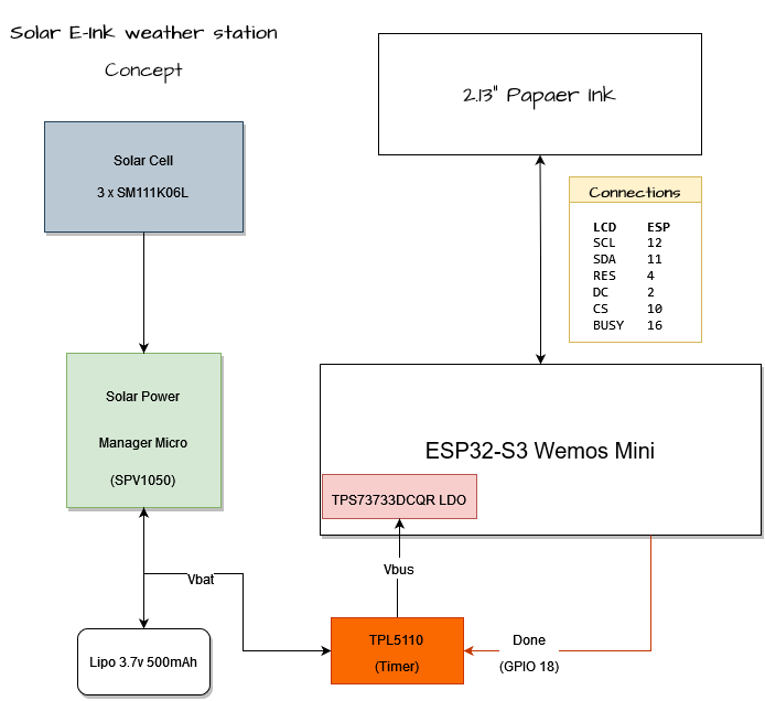
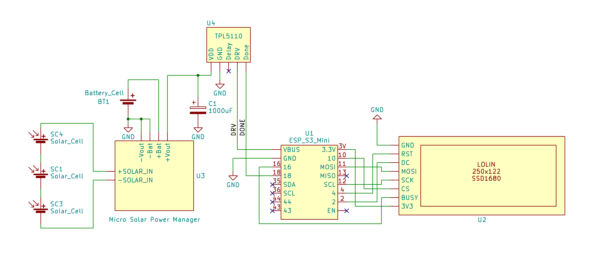
The concept chart above provides an overview of how the modules are interconnected. The solar cells provide energy to the energy harvesting module which will take care of loading the LiPo battery whenever the solar panels are generating energy. One of the particularities of this energy harvesting configuration is that it works even with very low input from the solar panel side ( as low as 0.5V). This makes it optimal for indoor energy harvesting.
Even though the ESP32 S3 has a good deep sleep characteristic, some uA are still required during this state. Since we are using a paper ink display, once it has been updated we don't need to keep providing energy to it anymore until the next update is required. Keeping in mind that the current consumption needs to be kept at its lowest to prevent the battery from running out of juice, a better solution than just relying on the ESP32´s sleep is required. This is the point where the TPL5110 comes into play.
The TPL5110 module enables a "clean" cut of power, lowering the standby consumption to the order of nano amperes. The TPL5110 can be programmed to wake up at a regular period and once the work is done, the ESP will signal it with the "Done" signal so the TPL5110 goes back to sleep and cuts off the current.
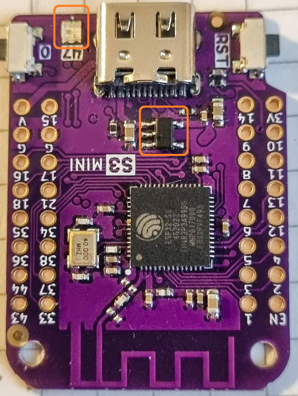
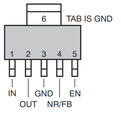
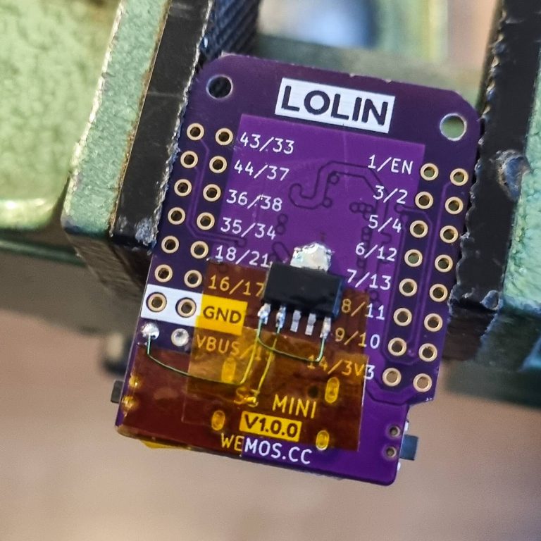
To keep the current as low as possible when the ESP32 is enabled, some changes need to be made to the ESP32 S3 Mini module. The changes consist of removing the RGB LED that has a "high" quiescent current and changing the integrated voltage regulator to something that fits better the purpose that we are trying to achieve. These steps are described later in this post.
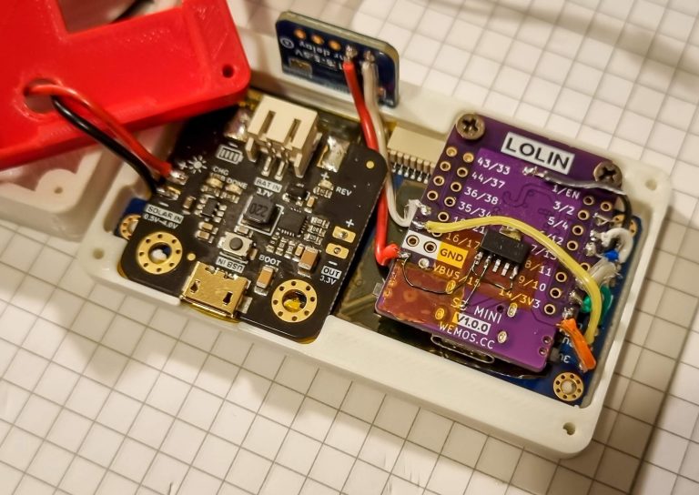
The setup described above has been running for months while mounted on a protoboard.
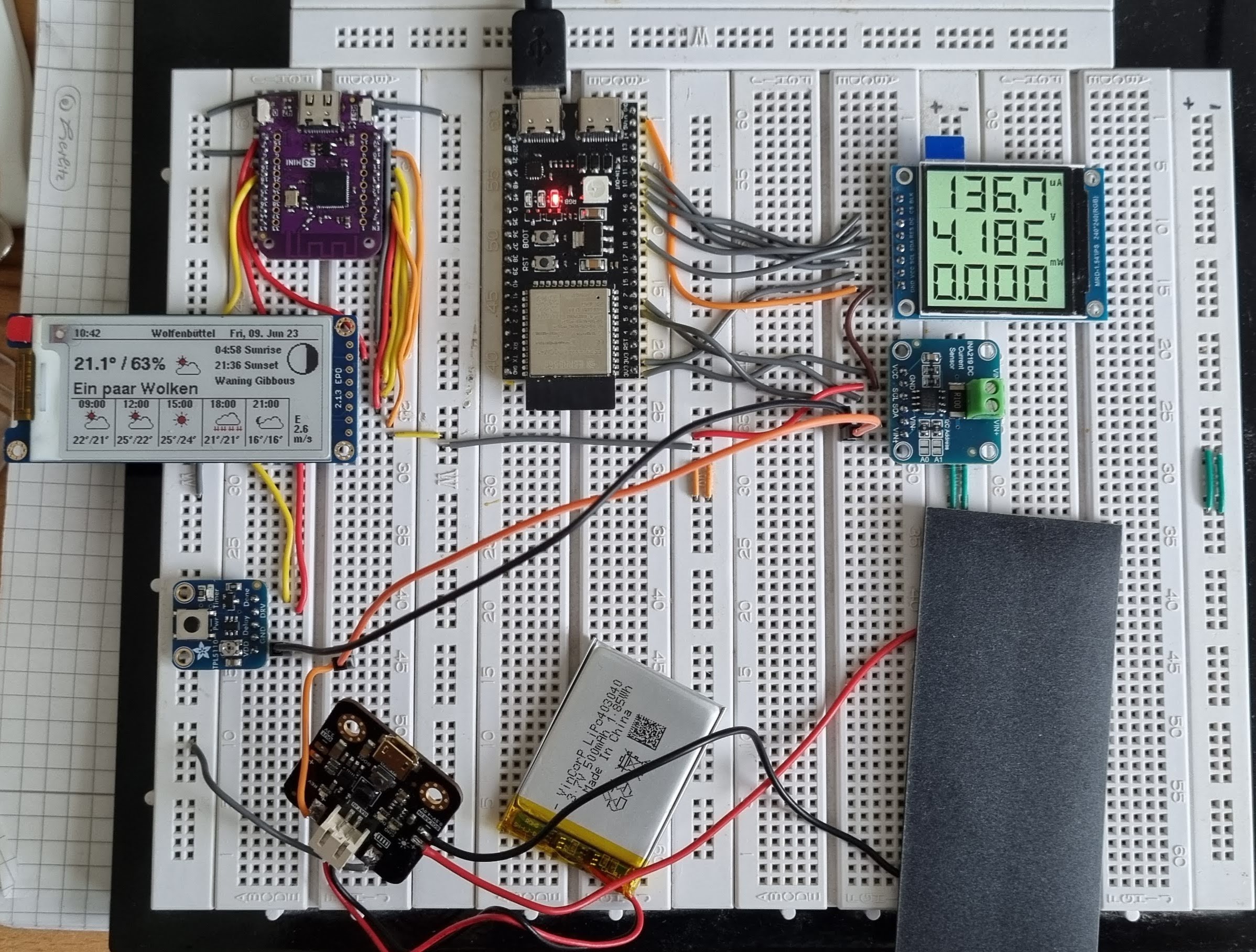

 For the cabling, it was helpful to have the chassis already printed so the cable lengths could be better estimated with all modules in place.


 alberto nunez
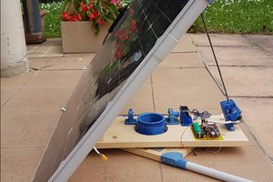
 JP Gleyzes
 Michel Kuenemann
 OzQube
meybe create a meshtastic device with solar power
or next creating a small computer. fuzix system on raspberry 2040 or similar