 Keith
KeithShould be pretty simple, I2C/SPI wires in and the parallel I/O pins simply routed to a 50-way connector.
Pinout shall follow this standard, with the first device driving groups 0 and 1, the second device driving groups 2 and 3.
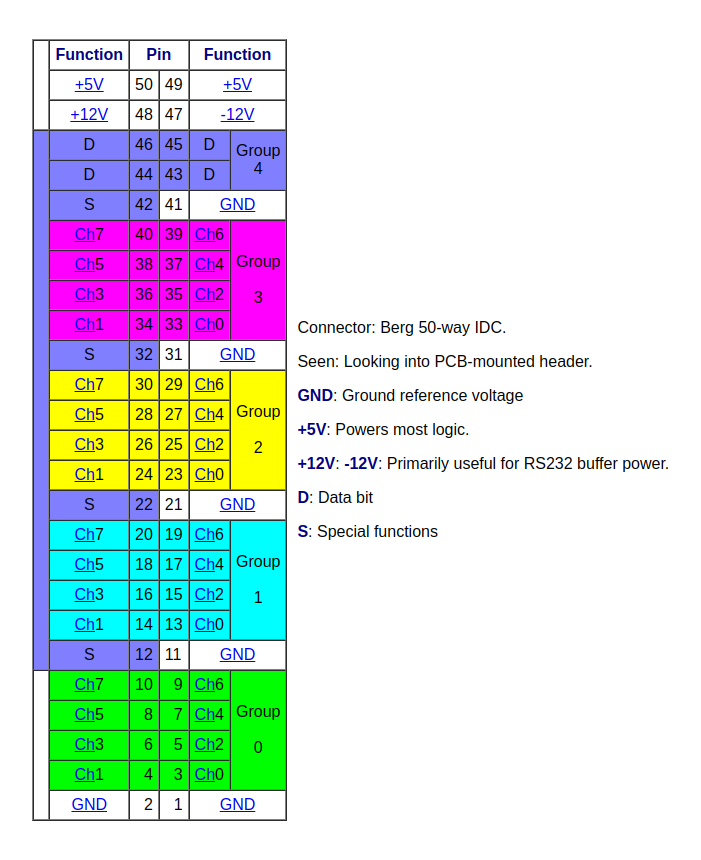
I shall omit:
- group 4
- special function pins
- -12V
But I will need:
- +12V if I want to drive my SCB11 relay board
- +5V for most signal conditioner boards
This will be a current supply problem because a USB-to-I2C/SPI board does not supply +12V at all, and the +5V rail does not have a lot of current available - I would guess 100mA or so. The LED32 indicator board will need about 400mA just to power all the LEDs on.
Some external power supply will thus be needed.
Discussions
Become a Hackaday.io Member
Create an account to leave a comment. Already have an account? Log In.