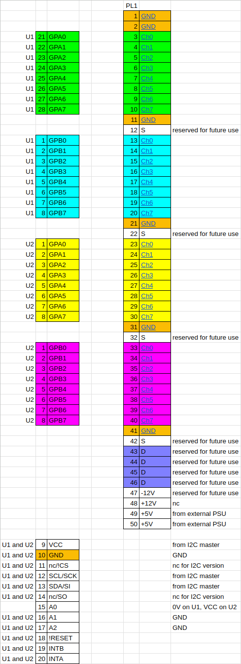
This is the proposed circuit. The two I2C to digital I/O chips are connected in their normal fashion, and the I/O pins connect to the Arcom I/O connector pins coloured in the diagram below. Mostly a join-the-dots exercise.
 I think the only "loose ends" are the interrupt signals, if used.
Most signal conditioner boards will assume they can take a fair amount of current from the +5, +12 and -12 volt pins, but of course the I2C master may not be able to supply that. More thought will be required to solve that issue.
 Keith
Keith
Discussions
Become a Hackaday.io Member
Create an account to leave a comment. Already have an account? Log In.