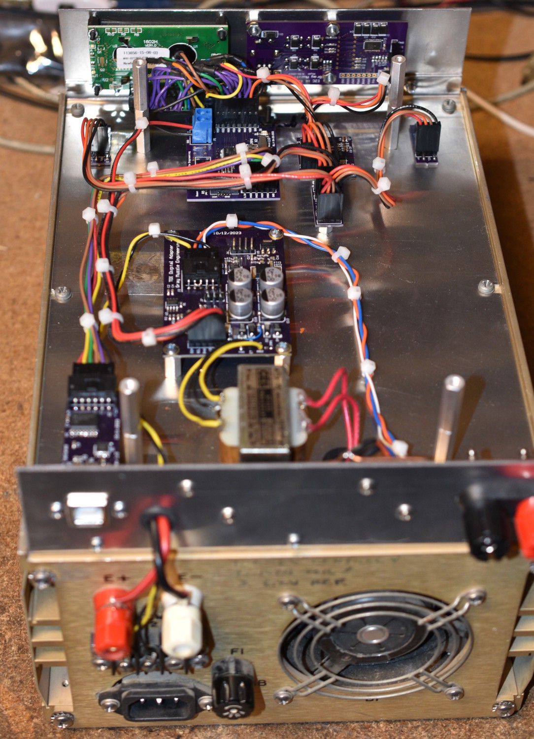
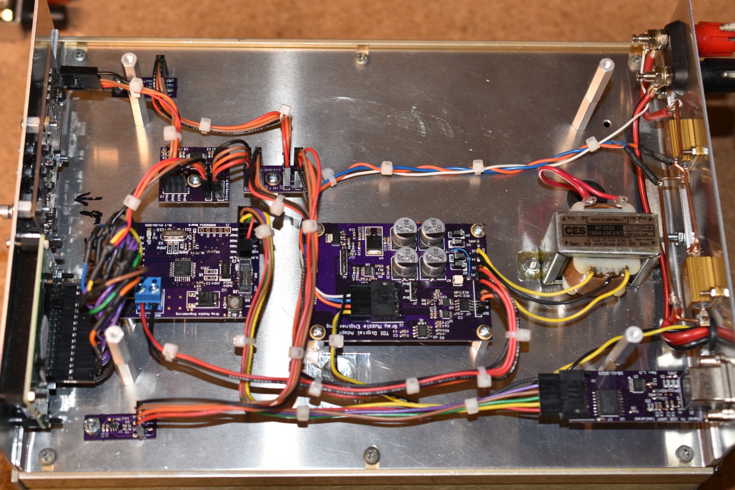
One of the goals on this project was to make as little modification to the original load box as possible. The mechanical construction of the unit helped with this. The top cover of the box is just a flat sheet of aluminum. This made a convenient place to put my electronics as sort of a backpack. Most of the connections to the load box are via terminals on the back of the unit. The only connections into the internals of the load box are the switched AC power source to feed the control hardware. A connector is added into the AC wiring on the load box to make it easy to remove the backpack.
A manual came with this unit, but it was for a different model that had much higher current and power handling capabilities. The schematic provided a rough idea of how the unit is wired, but there are significant differences between this load box and the manual. The manual showed that the control voltage range was 0V to +6V, which is a pretty convenient range to work with modern analog components. I verified this with a boat anchor power supply, a precision current sense shunt resistor, a good voltmeter, and a DC voltage calibrator. Taking a dozen measurements manually, the transfer function between control voltage and the current sink was checked and turned out to be fairly linear.
This load box will handle up to 50 volt inputs and sink up to 15 amps, with a maximum power level of 150Watts. It is also small enough to not take up an enormous amount of storage space when not in use.
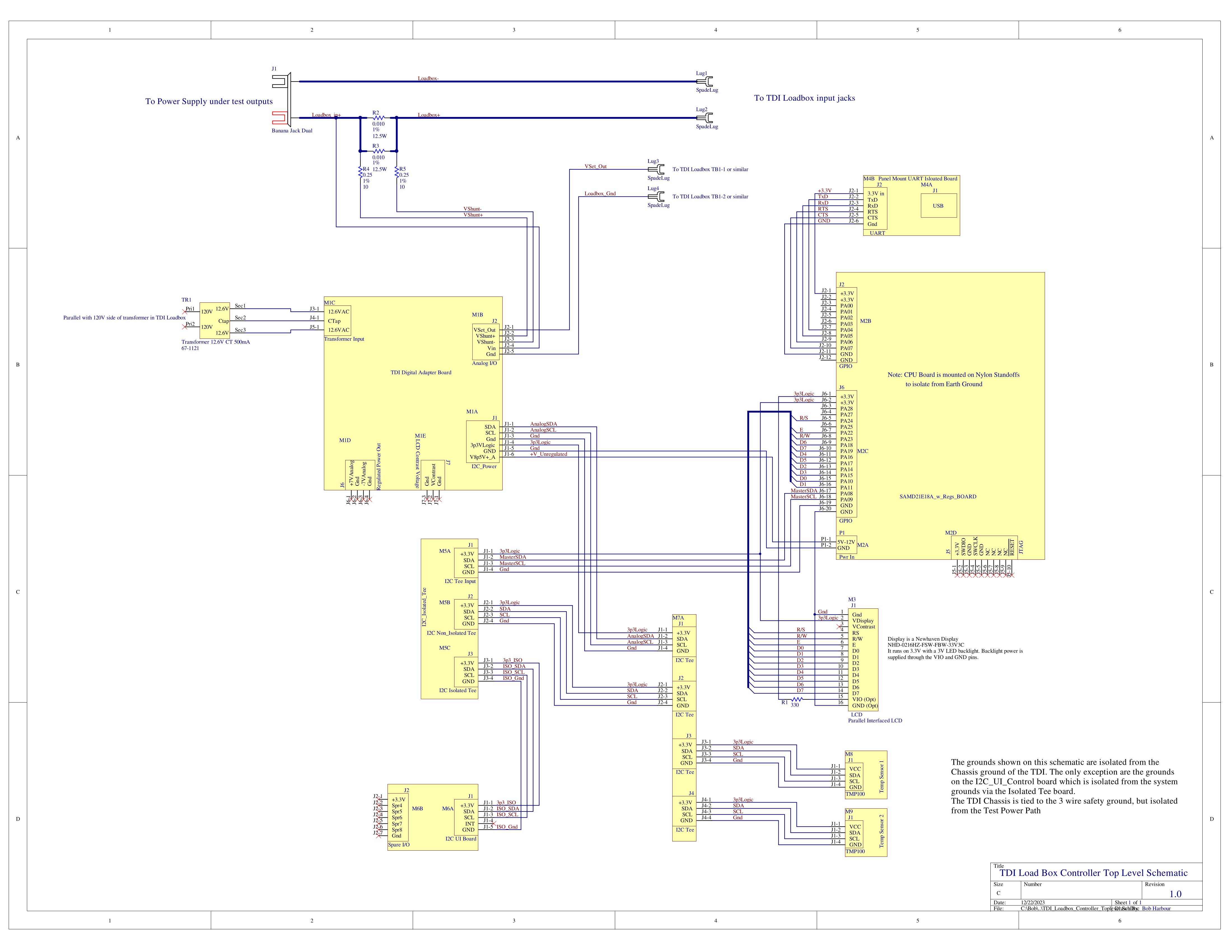
One of the issues with test equipment is the relationship of the test connections with the safety ground on the AC plug. Some instruments like scopes generally have the input grounds tied directly to the safety ground. Computers generally do too. Power supplies, and multimeters generally float the external connections with respect to the safety ground. This load box has it's input floating with respect to the safety ground. This is important because it is possible to have the safety ground become an unexpected short circuit, and with power supplies and load boxes, the currents may be large. I have seen a few destroyed USB ports on laptops and PCs as a result of this issue. I really wanted to preserve this isolation with my load box control stuff. Getting the grounds right on this project proved to be one of the more difficult parts.
Looking at the schematic in the manual for the larger load box, it indicated that the current was sensed with a 2 milliOhm resistor. This value would work well with the INA230 power monitor chip and I could re-use the signal from the internal current sense resistor. The INA230 has a maximum input voltage of 36 volts and allows using the sense resistor in the ground path so the current sense voltage would be close to ground. A voltage divider was placed in front of the voltage input of the INA230 to keep it's input voltage within the legal range while the load box could see up to 50V. Using these ideas, I designed the analog interface board. Testing this idea showed that the current sense resistors in the load box that I have are actually 33 milliOhms. This does not work with the INA230.
The signal ground in the load box is not the - power input binding post. Signal ground in the load box is on the far side of the current sense resistor from the - power input binding post, so the - input binding post sits below the load box signal ground by the current sense voltage. Control voltage to set the load current remotely requires a stable connection to the signal ground. To avoid problems between the control board analog ground and the load box signal ground, I decided to add my own current sense resistors on the + side of the input power. The INA230 will work with this configuration too. This choice limited the maximum input voltage to the load box to +36V, but for the work that I do, that is not a problem. A new set of input binding posts got added to the control back pack, with a 5 milliOhm sense resistor. The new - input binding post is tied to the load box - input binding post and the far end of the new current sense resistors goes to the load box + input binding post.
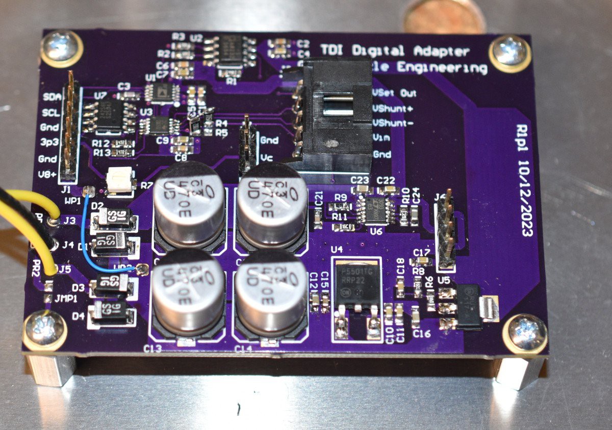
Control voltage for the load box is controlled by a 16 bit DAC whose output voltage is boosted with an op amp to the required 0 to 6V range. In order to get down very close to 0 volts, I used a bipolar power supply for the op amp. The analog voltages are regulated at +/- 7.0 Volts. A 12.6V center tapped transformer is mounted to the chassis to provide the system power. The analog board that I designed for this project has rectifiers, bulk filter caps, regulators, the INA230, the control voltage circuit and a non-volatile memory for holding calibration information. Ground on the analog board are not tied to the chassis.

Both the INA230 and the control voltage DAC (AD5693) are interfaced to the CPU board with an I2C bus. The CPU boards that I have don't include a non-volatile memory, so the analog board was a place to put it without adding extra wiring.

A SAMD21E18 MCU on a board of my own design was used to control this project. I have a lot of debugged infrastructure code for this chip and I had a couple of built up boards for it already. Unfortunately, the mounting bolt pads are tied to the power ground on this board. As a result, this board is mounted on nylon standoffs with nylon screws to keep the system ground isolated from the chassis ground.
A 16 character x 2 line LCD display is interfaced through the GPIO pins. The display mounting screw pads are also tied to the power ground, so it is mounted on nylon standoffs too.
I have some user interface boards left over from a previous project. These boards have 4 push buttons and a rotary encoder with a push button switch. Protecting the electronics on the user interface board from ESD pretty much requires a connection between the DC power ground and the chassis ground and a number of TVS diodes. The user interface board is also interfaced to the CPU via an I/O expander chip to the I2C bus. Isolating the user interface board is done with an Analog Devices ADM3260 I2C isolator chip. In addition to the I2C isolation, this chip also provides a few milliAmps of isolated power, which is enough to feed the user interface board. The TCA 9555 I/O Expander chip has internal pullup resistors on the I/O pins, so the pullup resistors on the switches and encoder were not populated for this board. Those redundant pullup resistors can push the board power consumption beyond the ADM3260s capability.
Distributing the I2C bus around this system is done with two T boards. A revision of the T board with the ADM3260 isolator chip allows the user interface board DC ground to be tied to the chassis ground for ESD protection without forcing the rest of the system ground to be connected to the chassis ground.
External communication with the system is via a USB to UART chip. I had an existing board layout with a nice sealed, rugged USB connector, but the USB ground was tied to the chassis ground and the power ground into the UART chip. Adding another isolator chip (TI ISO6742) solved that problem. The UART and the UART side of the isolator are powered from the USB VBus which is a sane configuration. The serial data signals cross the isolator chip and go on to the MCU. The MCU side of the isolator chip is powered from the regulator on the MCU board.
Load boxes tend to get pretty warm since all of the input power is dissipated as heat. To protect the system from getting too hot, I added a couple of TMP100 temperature sensors, also on the I2C bus. Mounting bolt pads on these boards are isolated from the power ground, so these boards are screwed to the bottom of the load box control chassis. I thought about mounting them directly to the heat sinks inside the load box, but there were no good places to do this, so I opted for the try the easy way and see how it works. So far, it seems OK. One other possible use for the temperature information may be in mapping the requested current to the DAC values. I need to investigate this farther.


Software
I wanted the remote interface to look like the command sets of other instruments that I am working with. Most of them use some dialect of the SCPI language. SCPI accepts shortened versions of commands, usually 4 characters. For example, the MEASURE command can be abbreviated as MEAS, or the whole word can be used. This drives the design of the command parser extensively. For parsing command line software on a PC, I break the command line down to word fields, much like the argc/argv arrangement and go for a full match on a command word. This approach will not work with the optional abbreviated commands. The SCPI language uses the colon character to separate command words, like: MEASURE:CURRENT. Parameters are usually separated from the command words with a space character like: STATIC:CURRENT 12.5. The parser that I used on this project looks for a match on the abbreviated command words and then looks for a colon or a space character to signify the end of that field. I call this progressive parsing. It makes for a messier looking parser, but it works.
Here is the command set that I have implemented:
- IDN ? returns Identification string with SW revision info
- :STATic:CURRent ? returns the static current setpoint
- :STATic:CURRent aa.aaa set the static current
- :STATic:MODE ? returns 1 if in static mode, else 0
- :STATic:MODE enter static mode
- :DYNAmic:HI:CURRent xx.xxx set the high current value for dynamic mode
- :DYNAmic:HI:CURRent ? returns the high current value for dynamic mode
- :DYNAmic:HI:TIME N_milliseconds set the time high for dynamic mode
- :DYNAmic:HI:TIME ? returns the time high for dynamic mode
- :DYNAmic:LOW:CURRent xx.xxx set the low current value for dynamic mode
- :DYNAmic:LOW:CURRent ? returns the low current value for dynamic mode
- :DYNAmic:LOW:TIME N_milliseconds set the time low for dynamic mode
- :DYNAmic:LOW:TIME ? returns the time low for dynamic mode
- :DYNAmic:MODE enter dynamic mode
- :DYNAmic:MODE ? returns 1 if in dynamic mode, else 0
- :MEASure:VOLTage returns the measured voltage at the backpack binding posts
- :MEASure:CURRent returns the measured current into the backpack binding posts
- :MEASure:RAW:VOLTage returns the ADC and calculated value for voltage at the binding posts
- :MEASure:RAW:CURRent returns the ADC and calculated value for current into the binding posts
- :MEASure:TEMP returns the measured temperature for the two sensors in the backpack
- :LOAD ? returns 1 if load is on, else 0
- :LOAD on/off turn the load on or off
- :SYSTEM:OTEMP ? returns 1 if measured temperature exceeds the overtemp threshold
- :SYSTEM:OTEMP:VALUE xxx.x set the overtemp threshold
- :SYSTEM:OTEMP:VALUE ? returns the overtemp threshold
- :SYSTEM:CALIbrate:RAW:ISET ? return the DAC value
- :CALIbrate:RAW:ISET int set the DAC value, may be decimal or hex
- :CALIbrate:COEFficient:I2V_SLOPE ? returns the slope coefficient for the current to voltage mapping
- :CALIbrate:COEFficient:I2V_SLOPE DEFAULT set the slope coefficient for the current to voltage mapping to default
- :CALIbrate:COEFficient:I2V_SLOPE 0.123 set the slope coefficient for the current to voltage mapping
- :CALIbrate:COEFficient:I2V_OFFSET ? returns the offset cofficient for the current to voltage mapping
- :CALIbrate:COEFficient:I2V_OFFSET DEFAULT set the offset coefficient for the current to voltage mapping to def
- :CALIbrate:COEFficient:I2V_OFFSET 0.123 set the offset coefficient for the current to voltage mapping
- :CALIbrate:COEFficient:MEAS_I_SLOPE ?
- :CALIbrate:COEFficient:MEAS_I_SLOPE DEFAULT
- :CALIbrate:COEFficient:MEAS_I_SLOPE 0.123
- :CALIbrate:COEFficient:MEAS_I_OFFSET ?
- :CALIbrate:COEFficient:MEAS_I_OFFSET DEFAULT
- :CALIbrate:COEFficient:MEAS_I_OFFSET 0.123
- :CALIbrate:COEFficient:MEAS_V_SLOPE ?
- :CALIbrate:COEFficient:MEAS_V_SLOPE DEFAULT
- :CALIbrate:COEFficient:MEAS_V_SLOPE 0.123
- :CALIbrate:COEFficient:MEAS_V_OFFSET ?
- :CALIbrate:COEFficient:MEAS_V_OFFSET DEFAULT
- :CALIbrate:COEFficient:MEAS_V_OFFSET 0.123
- :CALIbrate:NVM:READ Read the non-volatile memory into active memory
- :CALIbrate:NVM:WRITe Write the active memory into the non-volatile memory
- :CALIbrate:NVM:DEFAult Set the non-volatile memory to default values.
Capital letters indicate the required portion of a command, lower case letters indicate the optional portion of the command. This is just a documentation feature, the actual commands are accepted as upper or lower case characters. Multiple commands may be placed on a line with a semicolon ; separating them. Lines must be terminated with the Line Feed character (0x0A) to be accepted. Output lines will be terminated with the Line Feed character. One "misfeature" of my implementation is that for query commands, a space character must separate the ? from the previous section of the command. This is not consistent with the way SCPI is nornally done, and will probably get fixed later.
Some implementations of SCPI require a colon character to precede the first section of a command, and some don't. When using the semicolon to separate multiple commands on a line, it makes it more human readable, but it could be dropped just as easily.
Since I am using an MCU that I have used in multiple previous projects, I have a lot of the I/O type code already written and debugged. This includes serial data for the external interface, I2C for general use throughout the system, the user interface board, the nonvolatile memory handling, and the LCD interface. Interface for the INA230, DAC and the temperature sensors had to be written for this project.
Implementing the user interface software to accept the control inputs from the buttons and encoder and control the system setup was messy. the UI code is always my least favorite part of a project. I put that part off until the very end, and some of the design decisions made previously had to be re-worked. Ultimately, it all works now.
The architecture of the code has all of the hardware initialization, followed by variable initialization, then a loop. System operation is all implemented in the loop. A 1mS counter is running in the sys_tick interrupt. A lot of the local user interface is paced by the 1mS counter. In the main loop, presence of a command from the serial port is checked, and if the system is in dynamic mode, the 1mS time variable is checked to see if it is time to transition to the other dynamic state. Local user interface status is checked next. The local user interface status code is only run every 11 mS, as this is part of the debounce operation for the buttons and encoder. On loop iterations that do not run the local user interface, that portion of the code is just skipped, the rest of the loop is run. At the bottom of the loop, the measured voltage, current and temperature values get updated from the hardware.
None of the operations in the main loop are capable of blocking. If it is not time to do some action, skip over it and check the next time through the loop.
Minimum values for the times in dynamic mode are set at 10mS each for high and low current states. Timing for this operation is not terribly accurate, or fast, but neither are required for my use of the dynamic mode. In use, the power supply behavior around the transitions is what is being observed.
If one or both temperature sensors are indicating that the temperature is over the overtemp threshold, the load is switched off to prevent the temperature from rising more. Reseting the overtemp status must be done through the local user interface buttons, it cannot be done through the remote interface. This was done to insure that the user be involved in restoring the system.
System Stuff
Initially, I implemented a simple linear mapping from commanded current to DAC value. With a little bit of fooling with, it was reasonably accurate in the 1 to 5 amp range. As part of the firmware, I implemented a command that would allow setting the DAC value directly from a remote command.
In line with the other instrument stuff that I have been doing lately, I wrote a command line tool to talk to the load box over the USB/Serial connection.
In order to try to improve the accuracy of the current to DAC value mapping, I added a special scanning operation to the tool that drives my bench meter. This tool exec's the command line software tool that I wrote and sets the raw DAC value directly, then measures the load box current on the bench meter and gets the load box measured current and voltage values. This sequence gets repeated up to 512 times with increasing DAC values and the results written to a .csv file. The scan can also be run sending a current setpoint to the load box and making the same measurments.
Examining the data from a raw DAC setting scan, the slope of the DAC value to load current transfer function is pretty constant. As a result, I ran another scan using the current setpoint to set the load box current.
After comparing the current setpoint to the current measured on my bench meter, The setpoint current is within 2.5% of the measured current from about 750mA up through 15 Amps with the linear mapping and the coefficients that I came up with iteratively. Note that the second line of the display and the MEAS:VOLT and MEAS:CURR command display the voltage and current measured by the INA230 power monitor chip. The voltage measurement differs from the power supply voltage because of the resistance of the wiring and connections. The current measurement from the INA230 is pretty noisy and not terribly accurate. Both are useful for determining if there is a connection problem, but not control or calculations.
With the DAC value at 0 (the minimum value) the load box draws about 110mA. This is probably the current required to measure voltage and current in the load box. I am subtracting that out in the linear mapping, but the linearity of the mapping below about 750mA is a ways out, getting worse as the setpoint approaches 0. I may work on the mapping algorithm. I have one function that does that mapping for every place it is needed, so it would be a clean thing to do. Allternately, 2.5% is not too bad and I can live with that for 99% of what I want this tool for. I have not decided whether I am going to go after the mapping issue or not.
Things Still To Do
Powdercoat the front panel and the top cover. Done 1/2/2024
Label the controls on the front panel. Done 1/2/2024
Label the new input binding posts for voltage range. Done 1/2/2024
Maybe work on the mapping algorithm and coefficients.
Maybe work on the calibration for the INA230 current measurments. Done 1/5/2024
 Bharbour