Yaaay! got a busy year (wedding and stuff) and finally got back to this project again. Thanks to T.V. we got another iteration of the board.
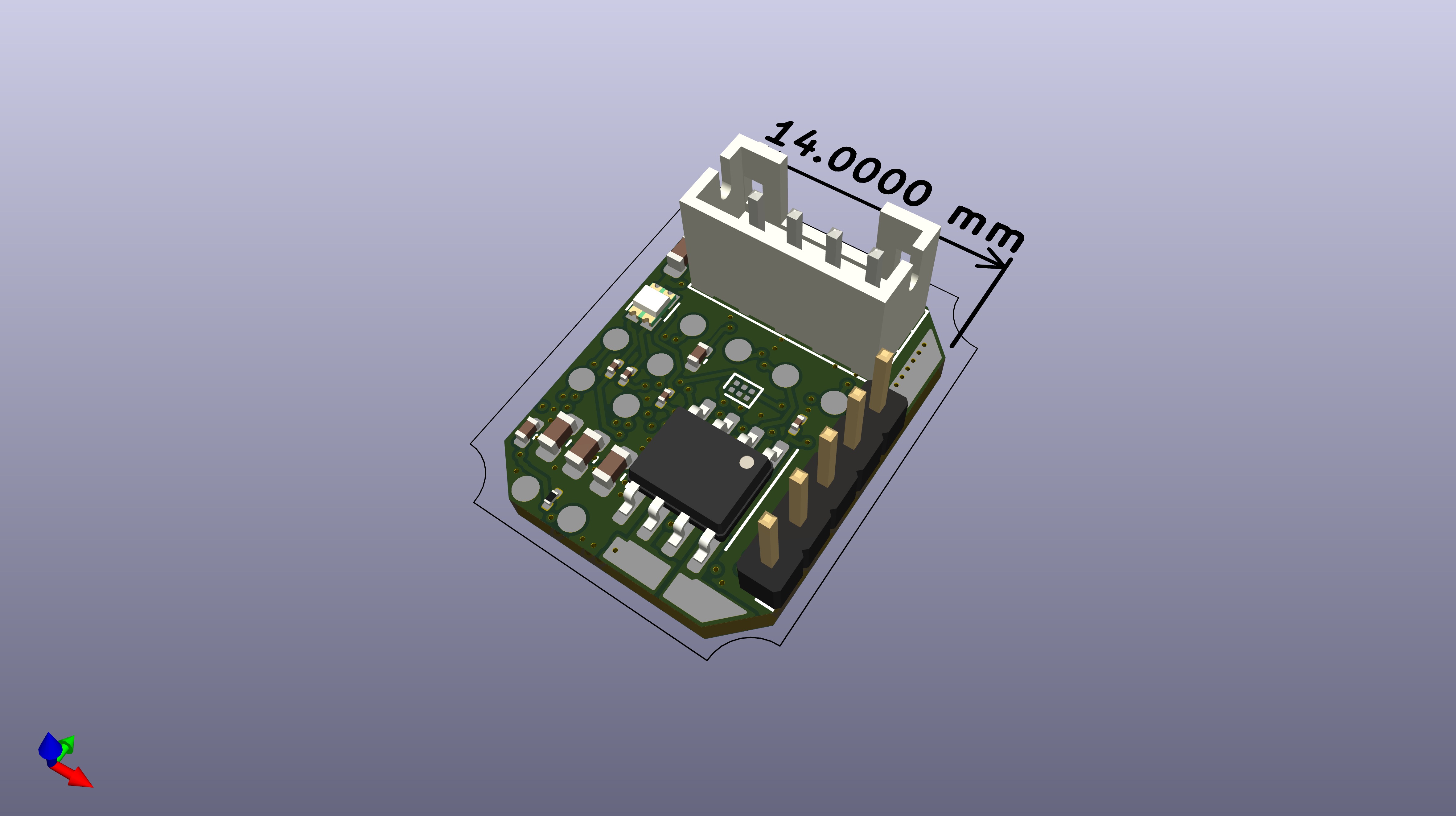
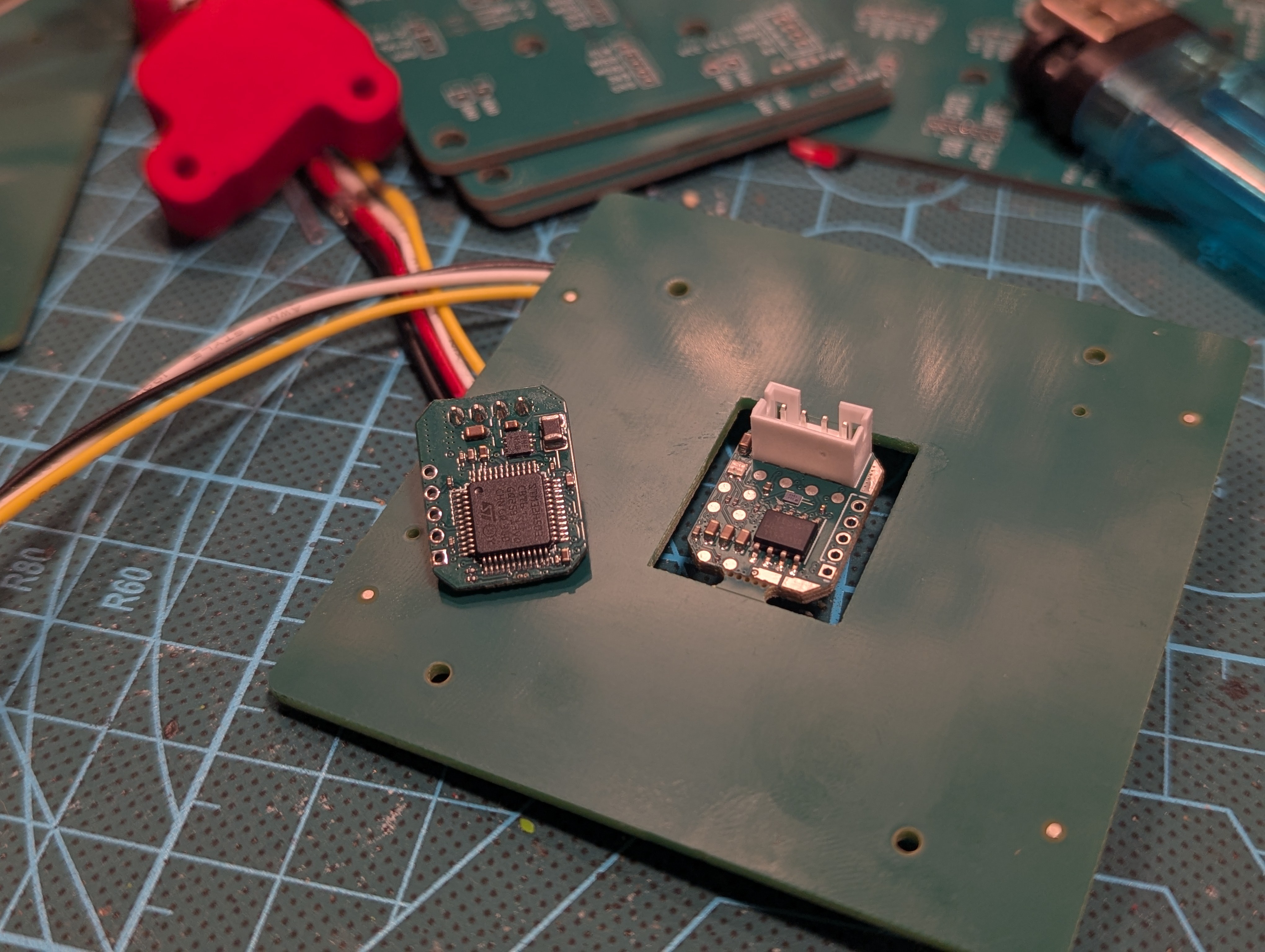
The new design is tad bit smaller and with some iterative changes. The main goal was to get rid of directly connected debug board and move to pogo pins, ideally this should've been the final version. (Obviously it is not) Out of the new features: we got i2c memory chip! no need to play with internal flash anymore.
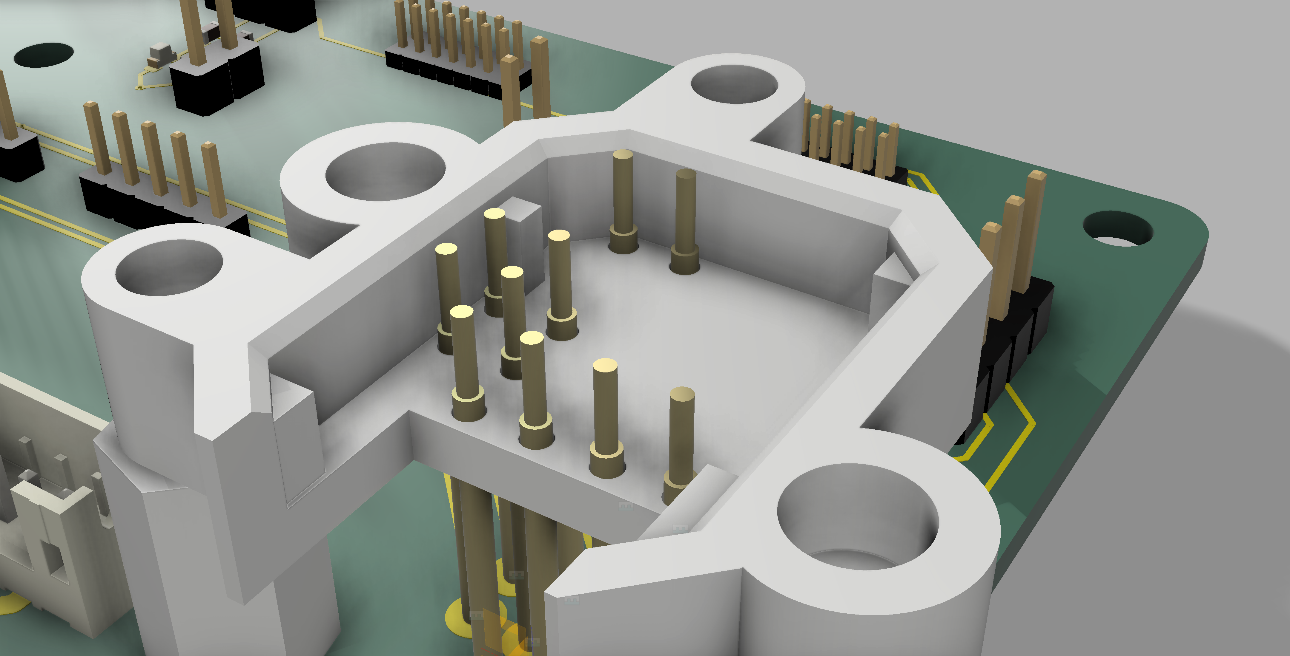
Testjig
First version of testjig proved to be impractical, the idea was to create a "cap" that encapsulates the board, this did not work great:
- The board was not accessible for attaching debug probes/stuff
- The alignment of pins was not perfect
- The board tilted a bit inside under the pressure from the pins
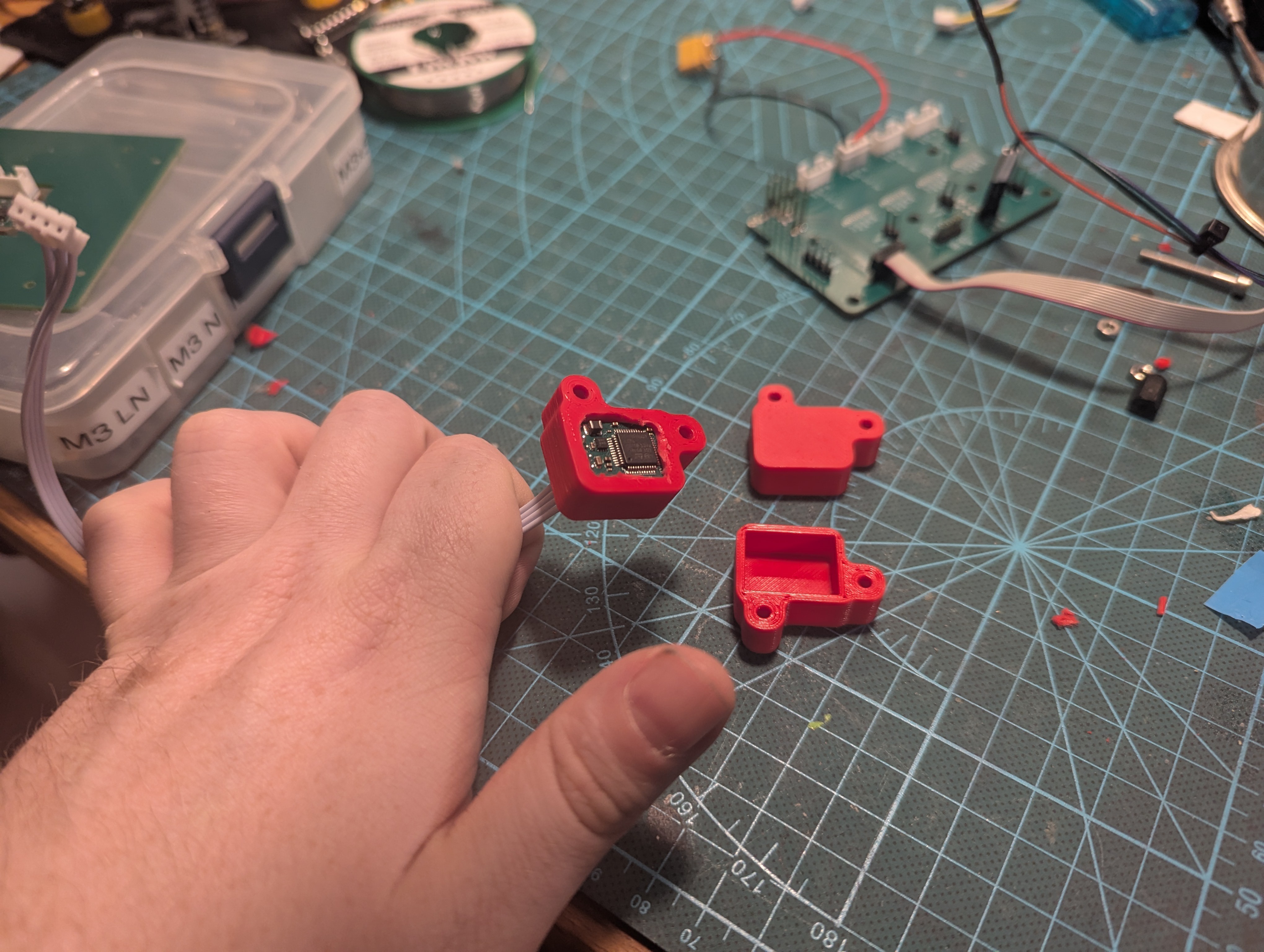
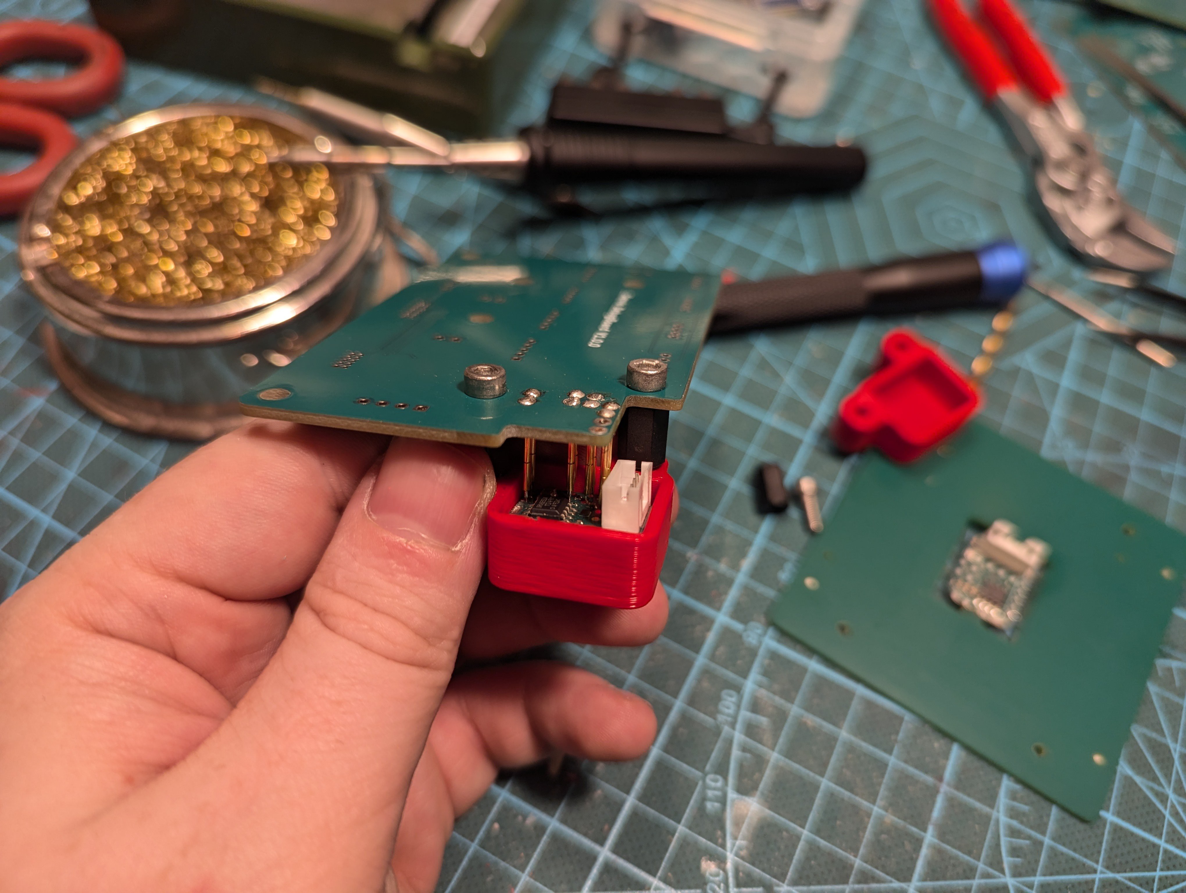
I think that the root cause is the idea of the cap. Instead I started remodelling the holder into two-part system - there will be part holding the PCB from the bottom side and part holding it from the top site. Both will be connected together to hold all in place (magnets?)
Hopefully I can get this over soon over the holidays and soon got to programming this thing! :)
Discussions
Become a Hackaday.io Member
Create an account to leave a comment. Already have an account? Log In.