 Smalls
Making the Fox Head
I'd never made a puppet head before but I'm pretty crafty and during my cosplay days I'd discovered the material Worbla, which is a thermoplastic that can be easily shaped when heated and has adhesive on one side that is also heat activated. When it cools it retains its shape and can be reheated over and over again. I've previously used it to make some pretty cool armor and uniquely shaped props so I thought it would be just what I needed.
That said, I always do better when I have a shape to place the Worbla over, so I headed over to thingiverse.com to see if there were any fox skulls 3D print designs that looked promising.
I found a Fennec Fox Puppet head base created by Tioh:

I scaled it down using my 3D printer slicer software Flash Print to be about 3-4 inches wide and sent it off to print. After a successful print, I began to cut out small pieces of Worbla and began applying it to the outside of the print with the shiny side facing out as this is the adhesive side that we'll need later to stick the fur to:

IMPORTANT: Heat the Worbla pieces away from the 3D print, as the PLA will start to warp when too much heat is applied.
After the 3D skull was completely covered with Worbla I cut out a section of faux fur and shaved it down using a beard trimmer. Don't go as short as you want the finished project as you'll do some more trimming once everything is assembled, but getting some of the bulk of the fur removed early on is helpful for attaching it to the 3D printed skull. This was SUPER messy, do this outside if you can.


I then traced lines on the back radiating out from areas I knew it would have to curve around the shape of the skill, generally radiating from the bridge of the nose. Using a utility knife, I carefully cut the lines.
Make sure to only cut through until the base of the fabric separates, do not chop any of the fur on the other side.

I then heated the Worbla on the 3D printed skull and began sticking the fur to the activated adhesive. This part is tricky because your PLA will also get warm enough to start to warp so as it cools make sure you're helping the plastics reform to the right positions. You may need to cut a few extra lines, trim off excess or otherwise manipulate the fabric to be where you need it.
I also had to cut a few extra few extra pieces that I did not trim the fur on that would go behind the ears so it was a smooth transition when I eventually create a body for the fox.
This wasn't an exact science, do what you have to do to make it look right.


I then trimmed out the eye shape with sharp pair of embroidery scissors.

The ears were created using trimmed down fur of the same color as the head and also some trimmed down white fabric. I didn't capture photos of the process but here are the step I followed:
1. Cut out a triangle shape out of cardboard and cut a slightly curved line along the bottom that follows the general slop of your fox head where the ears will be places.
2. Use this as a template to cut out the Worbla, make sure to flip the template over for the second one, as you need ears sloping in opposite directions.
3. Cut out fur slightly bigger than your template.
4. Cut a wooden dowel about 2 inches long, The dowel should be around 1/4 inch thick or less but don't go too thin.
5. Heat your Worbla to the point where it feels stick on both sides and put your dowel so it's 1/2 inch from the bottom of the ear in the center of your ear. Place your normal fur color to one side, and the white fur to dowel side, press firmly until cooled.
6. Re-heat and gently shape the ear so it has a small rounded fold around the edges and gently curve over all.
7. Repeat for the other ear.
8. IMPORTANT: WAIT TO DO THIS STEP UNTIL YOU'RE READY TO MOUNT YOUR SEVOS. See further down in the instructions. Drill holes in the head the size of your dowel where the ears should be placed and insert ears. They should swivel freely without resistance when you try to move them.
Next I made eye lenses so the eyes would have depth and reflection. I used the oval shape from this mold on Amazon and some clear hard cast resin. I then attached the lenses using some Worbla (always save your scraps!).

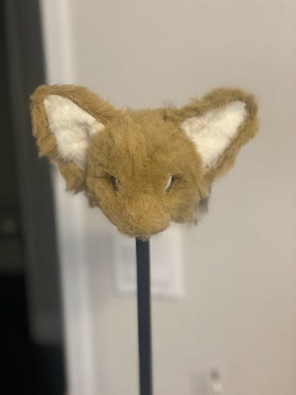
And that's it you've got a fox head ready for some tiny screens and servos! Along the way your head might have gotten warped. Don't be afraid to re-heat it and shape it back to how it's supposed to look.
Programming and Mounting the Eyes
This section primarily a repost of this project I did earlier but does have some new information related to mounting the eyes on the skull at the end.
Before You Get Started
I started with absolutely ZERO experience with Linux, Raspberry Pi, and SPI devices. Here’s some things I learned along the way that may be helpful to a beginner like me:
- Press enter to execute your command lines
- To paste code, copy it like you would any normal text from your resource (webpage, text file, etc.) and then in the Pi command prompt window, right click with your mouse and it should paste
- To use a recent command press up in the command prompt window to cycle through recent ones used
Helpful commands:
cd ~ will take you to the home directory
cd.. will take you one folder back
ls will list files in the folder you’re currently in
If you veer off this tutorial to troubleshoot or find other options please note that anything you find with OMXplayer will no longer work. It was depreciated a year or so ago and it's core library is not available to download. This also means that the Adafruit Video Looper tutorial does not work anymore. I went down a ton of frustrating rabbit holes that were all reliant on the OMXplayer either obviously or not so obviously before cobbling together a solution with the VLC player.
Important Notes
This will only work with a 32-bit version of the Raspberry Pi OS with desktop and was last tested on 12/9/2023 with Bullseye 11.
Wire Your LCD Screen
Wire your LCD screen to your Pi according to the wiring diagram here:
https://www.waveshare.com/wiki/1.14inch_LCD_Module
Image Raspberry Pi V
1. Download and install the Raspberry Pi Imager: https://www.raspberrypi.com/software/
2. Launch Program and install Pi Os with Desktop
I used Bullseye 11 (12/5/2023 version listed in the Imager)
3. I like to pre-configure settings and recommend you do so as well:
Set username and password, configure wireless lan, and set locale settings:

Enable SSH incase you ever need it:

Boot and Setup Your Pi
Put your micro SD card into your Pi, connect a monitor, keyboard and mouse combo (or use a USB hub to use two separate devices), and lastly power
1. Connect Your Pi: Put your micro SD card into your Pi, connect a monitor, keyboard and mouse combo (or use a USB hub to use two separate devices), and lastly power
2. Allow the Pi OS to fully boot and open the Desktop
Connect via SSH
1. On your PC computer go to the search bar and type CMD to open a Command Prompt window
2. Ping Your Pi: Type: ping raspberry.pi You should get results back from the ping, if not, try waiting a minute or two, your pi may still be loading. If that still doesn’t work, make sure your Pi is not in the Looper program
3. SSH into your Pi, type: ssh pi@raspberrypi Login is the same as previous steps
You are now connected and can continue setting up your Pi from the PC desktop in the Command Prompt window!
Enable SPI
1. Enter config settings by typing: sudo raspi-config
2. Choose Interfacing Options -> SPI -> Yes to enable SPI interface
3. Exit
Configure Pi for LCD Screen
These steps are directly from https://www.waveshare.com/wiki/1.14inch_LCD_Module with minor modification for clarity. Enter each of these commands and let finish before moving to the set.
1. Install BCM2835 Libraries:
wget http://www.airspayce.com/mikem/bcm2835/bcm2835-1.71.tar.gz
tar zxvf bcm2835-1.71.tar.gz
cd bcm2835-1.71/
sudo ./configure && sudo make && sudo make check && sudo make install
2.Install WiringPi libraries
cd ~
sudo apt install wiringpi
For Raspberry Pi systems after May 2019 (earlier than that can be executed without), an upgrade may be required:
wget https://project-downloads.drogon.net/wiringpi-latest.deb
sudo dpkg -i wiringpi-latest.deb
gpio -v
(Run gpio -v and version 2.52 will appear, if it doesn't it means there was an installation error)
3. Install Python Libraries
sudo apt-get update
sudo apt-get install python3-pip
sudo apt-get install python3-pil
sudo apt-get install python3-numpy
sudo pip3 install RPi.GPIO
sudo pip3 install spidev
4.Test Your Screen, download examples:
d ~
sudo apt-get install unzip -y
sudo wget https://files.waveshare.com/upload/8/8d/LCD_Module_RPI_code.zip
sudo unzip ./LCD_Module_RPI_code.zip
5.Compile and Run Code
cd LCD_Module_RPI_code/RaspberryPi/
cd c
Sudo make clean
sudo make -j 8
cd ~
6.Run an Example
cd LCD_Module_RPI_code/RaspberryPi/python/example
ls -l
sudo python3 1inch14_LCD_test.py
Your screen should now be displaying a test image! This is also where you'll use a different code from waveshare to test is your screen size is different than mine.
Install VLC Player (do this BEFORE setting up FBCP)
Install VLC Player (do this BEFORE setting up FBCP)
In your open Command Window, ensure your Pi is entirely up to date, type:
1. In your open Command Window, ensure your Pi is entirely up to date, type:
cd ~
sudo apt update
sudo apt upgrade
2. Install VLC, type:
sudo apt install -y vlc
Add Your Video Your Pi via SCP
This requires you to be able to connect to the Raspberry Pi from your PC. Your Raspberry Pi OS install at this point already has a folder called Videos, so we’ll be using that destination for your files.
1. Move your video file to your desktop on your PC
2. Open a Command Prompt window: Click your start bar search and type cmd to open a Command Prompt on your PC
3. Connect to your Pi via SSH, type:
ssh pi@raspberrypi.local
Type yes if promoted and then login with your pi password.
4. Open a second command prompt window and send files via SCP, type:
cd desktop
scp filenameofvideo.mp4 pi@raspberrypi.local:~/Videos
Your result should show your file name and the a 100% indicator. Repeat as many times as needed for whatever videos you’d like to have play on startup!
Make VLC Autostart, Full Screen and Play from your Videos Folder
Make VLC Autostart, Full Screen and Play from your Videos Folder
Instructions were taken from here with slight modification: https://forums.raspberrypi.com/viewtopic.php?t=17051
IMPORTANT: Do not use sudo on any of these commands or it will set permissions in a way that the pi user that is automatically logged in will not be able to use it and it will not autostart.
1. Create an Autostart directory, type:
mkdir /home/pi/.config/autostart
2.Create a.desktop file with the instructions for autostarting VLC and looping the video with no video title, type:
nano /home/pi/.config/autostart/autovlc.desktop
Add the lines:
[Desktop Entry]
Type=Application
Exec=/usr/bin/vlc -f -- random --loop --no-video-title /home/pi/Videos
Press CTRL X and type Y for yes when asked to save
4. Reboot your Pi, type:
Sudo reboot
Make sure your Pi is hooked up to a monitor, you should be able to see the VLC player load, full screen, play your playlist and loop back to the start of the playlist when at the end! Important: Your video will not yet be playing on your small LCD screen, you will need to complete the FBCP Porting steps.
FBCP Porting
This will mirror your HDMI output to your SPI LCD. These steps are from: https://www.waveshare.com/wiki/1.14inch_LCD_Module
Important: If following the directions directly on the waveshare page linked above, the script function would not work for me and I had to use the manual instructions to finish setup. I believe this has something to do with the newer Pi OS.
1. Install the drivers, type:
cd ~
sudo apt-get install cmake -y
wget https://files.waveshare.com/upload/1/18/Waveshare_fbcp.zip
unzip Waveshare_fbcp.zip
cd Waveshare_fbcp/
sudo chmod +x ./shell/*
2. Remove the conflicting DRMVC4 statement, type:
sudo nano /boot/config.txt
Delete this section:

CTRL X to exit, Y to save
3. Reboot the pi, type:
sudo reboot
4. Configure, compile and run, type:
cd Waveshare_fbcp/
mkdir build
cd build
sudo cmake -DSPI_BUS_CLOCK_DIVISOR=20 -DWAVESHARE_1INCH14_LCD=ON -DBACKLIGHT_CONTROL=ON -DSTATISTICS=0 ..
^^ (from sudo to =0 is all one line, make sure to copy the whole thing)
sudo make -j
sudo ./fbcp
This is another place where you'll use different code if your screen is a different size than mine. Change the line that starts with sudo cmake with the appropriate one from the waveshare website linked above.
5. Setup this functionality to start automatically when you boot your Pi, type:
sudo cp ~/Waveshare_fbcp/build/fbcp /usr/local/bin/fbcp
sudo nano /etc/rc.local
Add fbcp& before exit 0.
Important: You must add "&" to run in the background. Otherwise, the system may not be able to start.

Important: My video files are already formatted for my screen resolution when I create them. Yours may not be be, so if things look wonky, check out the final steps in the waveshare guide for setting the display resolution: https://www.waveshare.com/wiki/1.14inch_LCD_Module#Set_the_Display_Resolution
Add a Second SPI LCD
1. Splice together the wires of both screens and put a male pin connector on the end

2. Plugin the wires to the Pi exactly how you did previously
When your Pi boots, it should be playing the same video on both screens.
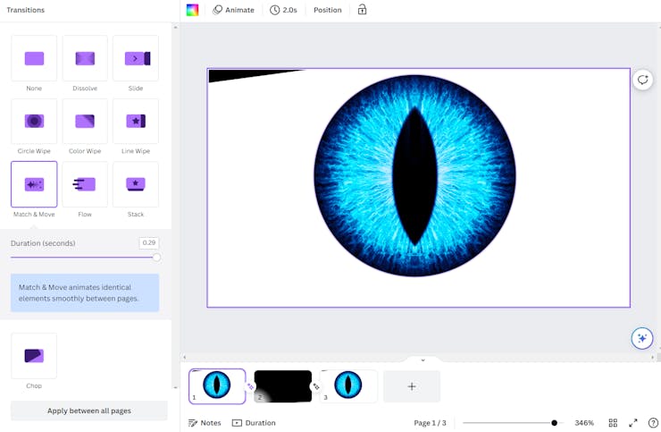
Creating the Eye Animations
I don't have any experience with animation software so I just used Canva and used the slide transition Match & Move to make several videos where the eyes either blinked or moved left/right. I also created a few videos where the eye didn't move that were just specific durations such as 5 seconds and 10 seconds. Having still animations that the playlist. I've included my files where the canvas is set to the right size for the resolution of the eyes.
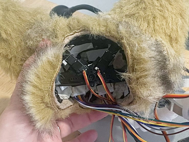
Mount the Eyes
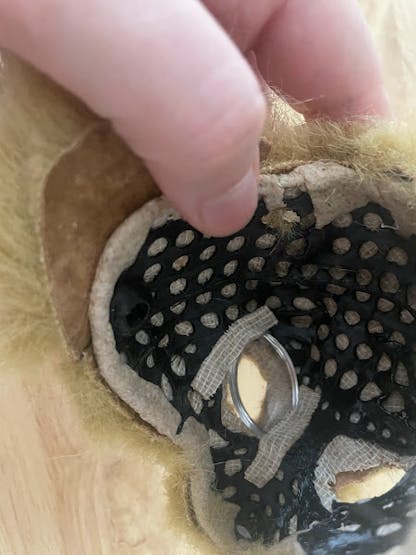
First put globs of mounting putty on front and back corners of your screens. GENTLY get your screens into position resting flat against the lenses on the inside of the skull. If you press too hard your screens WILL break.
I recommend having your screens on with the animation playing so you can see where you're positioning your eyes. When you're happy with the placement carefully place mounting tape all around the edges of the back of the screen and the inside of the skull.

Programming and Mounting the Servos
This section primarily a repost of this projectI did earlier but does have some new information related to mounting and connection of the servos.
Notes: This project assumes you have Arduino IDE setup and know how to connect and write to an Arduino Uno board.
Hook Up Your Servos
The first step is to hook up your servos to your UNO. If you purchased the same servos I used from Amazon the wires are as follows:

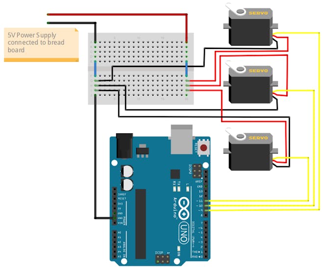
The Uno has issues powering servos consistently at 5V and you'll be hooking up multiple servos to 5V, so I recommend using an 5V power supply.
The signal wires will connect to Uno Pins 9, 10, and 11 and the servo power and ground will connect to the power supply. ** Make sure you connect your power supply's ground to your Uno's ground**

Write Sketch and Upload the Code
Plug your Uno into your computer and open a new sketch in Arduino IDE. Copy and paste the code from the code section of this project.
#include

//original code transcribed from Mike Theevil's video:
//modified by Smalls on Nov 8 2023

Servo rear; //create servo object to control a servo
Servo lear; //create servo object to control a servo
Servo head; //create servo object to control a servo
// twelve servo objects can be created on most boards

void loop_rear() {
 int r1 = random(10, 90); //defines variable and sets servo step amount between 0 and 170 degrees
 int r2 = random(500, 2000); //defines variable and sets random delay
 int r3 = random(2000, 10000); //defines variable and sets neutral random delay

 rear.write(r1); //makes servo position random
 delay(r2); //triggers random relay
 rear.write(90); //resets servo to neutral position
 delay(r3); //triggers neutral random delay
}

void loop_lear() {
 int l1 = random(90, 170); //defines variable and sets servo step amount between 0 and 170 degrees
 int l2 = random(500, 2000); //defines variable and sets random delay
 int l3 = random(2000, 10000); //defines variable and sets neutral random delay

 lear.write(l1); //makes servo position random
 delay(l2); //triggers random relay
 lear.write(90); //resets servo to neutral position
 delay(l3); //triggers neutral random delay
}

void loop_doubleear() {
 rear.write(10); //right ear at 10
 lear.write(170); //left ear at 170
 delay(1000); //delay for
 rear.write(90); //makes servo position random
 lear.write(90); //resets servo to neutral position
}

void loop_head() {
 int h1 = random(40, 140); //defines variable and sets servo step amount between 0 and 170 degrees
 int h2 = random(500, 2000); //defines variable and sets random delay
 int h3 = random(2000, 10000); //defines variable and sets neutral random delay

 head.write(h1); //makes servo position random
 delay(h2); //triggers random relay
 head.write(90); //resets servo to neutral position
 delay(h3); //triggers neutral random delay
}

void setup() {
  rear.attach(9); //attaches the servo on pin 9 to the servo object
  lear.attach(10); //attaches the servo on pin 9 to the servo object
  head.attach(11); //attaches the servo on pin 9 to the servo object
}

void loop() {
  byte randNum = random(4); //max range of numbers
  switch (randNum) //switches between the random numbers assigned in this loop
  {
    case 0:
      loop_rear();
      break;
    case 1:
      loop_lear();
      break;
    case 2:
      loop_head();
      break;
    case 3:
      loop_doubleear();
      break;
  }
}
Understanding the Code
- Servo tail; //create servo object to control a servo Create one of these for each servo you have, you can replace "tail" with a unique name of your choosing
- void loop_tail() create a loop for each servo, make sure to name it the same thing as your servo so you don't forget which loop controls which servo
- int t1 = random(0, 170); defines variable and sets servo step amount between 0 and 170 degrees
- int t2 = random(500, 800); defines variable and sets random delay in microseconds
- int t3 = random(400, 1000); defines variable and sets neutral random delay in microseconds
- tail.write(t1); sets the servo to a random position according to the range defined in int t1
- delay(t2); pauses movement for a random amount of time according to the range defined in int 2
- tail.write(0); resets the servo to its neutral starting position
- delay(t3); pauses movement for a random amount of time according to the range defined in int 3
- void setup() is run one to setup your board and pins
- tail.attach(9); attaches the servo on pin 9, each servo would get a line of code attaching it to its own pin
- void loop() this is where you'll list all the servo loops you created to be triggered at random
- byte randNum = random(3); creates a max range of random numbers that can be assigned
- switch (randNum) switches between the cases listed
- case 0: the number assigned to the loop which will be called upon with the switch command, if you add another loop to be controlled it would be case 1, followed by case 2 and so on
- loop_tail(); the name of the loop you want to run when the case number is randomly picked
- break; Tells the program to go back to the switch command and pick a new number as opposed to moving to the next case number in the sequence.
Servo and Uno Circuit Diagram
How to connect the servos, uno, and power supply.
Randomized Multiple Servo Code
This code is different than the linked project above and has been calibrated to add in pauses and specific angle limitations to prevent the head from seeming uncanny in its movements.
#include <Servo.h>//original code transcribed from Mike Theevil's video: https://www.youtube.com/watch?v=1doy5nNS-cg//modified by Smalls on Nov 8 2023Servo rear; //create servo object to control a servoServo lear; //create servo object to control a servoServo head; //create servo object to control a servo// twelve servo objects can be created on most boardsvoid loop_rear() {int r1 = random(10, 90); //defines variable and sets servo step amount between 0 and 170 degreesint r2 = random(500, 2000); //defines variable and sets random delayint r3 = random(2000, 10000); //defines variable and sets neutral random delayrear.write(r1); //makes servo position randomdelay(r2); //triggers random relayrear.write(90); //resets servo to neutral positiondelay(r3); //triggers neutral random delay}void loop_lear() {int l1 = random(90, 170); //defines variable and sets servo step amount between 0 and 170 degreesint l2 = random(500, 2000); //defines variable and sets random delayint l3 = random(2000, 10000); //defines variable and sets neutral random delaylear.write(l1); //makes servo position randomdelay(l2); //triggers random relaylear.write(90); //resets servo to neutral positiondelay(l3); //triggers neutral random delay}void loop_doubleear() {rear.write(10); //right ear at 10lear.write(170); //left ear at 170delay(1000); //delay forrear.write(90); //makes servo position randomlear.write(90); //resets servo to neutral position}void loop_head() {int h1 = random(40, 140); //defines variable and sets servo step amount between 0 and 170 degreesint h2 = random(500, 2000); //defines variable and sets random delayint h3 = random(2000, 10000); //defines variable and sets neutral random delayhead.write(h1); //makes servo position randomdelay(h2); //triggers random relayhead.write(90); //resets servo to neutral positiondelay(h3); //triggers neutral random delay}void setup() {rear.attach(9); //attaches the servo on pin 9 to the servo objectlear.attach(10); //attaches the servo on pin 9 to the servo objecthead.attach(11); //attaches the servo on pin 9 to the servo object}void loop() {byte randNum = random(4); //max range of numbersswitch (randNum) //switches between the random numbers assigned in this loop{case 0:loop_rear();break;case 1:loop_lear();break;case 2:loop_head();break;case 3:loop_doubleear();break;}}
Mount Your Servos
I created mounting brackets and connectors for my servos in Fusion 360 and have attached the STL to this project.

1. Is a cross sectional bracket that will be glued to the inside of the skull under where the ears go and will hold the two ear servos.
2. Is a mounting bracket to hold the larger servo that controls the head tilt and is connected to whatever will be your spine apparatus. I designed the mounting hole to be compatible with this poseable ball socket armature, but I may swap this out for something else later.
3. Print 2 of these, they're the connectors between the small servos and the dowels extending from your fox ears.
Place the #1 cross sectional bracket where you want it in the skill, with the servo slots pointing towards the top of the head and hot glue in place.
Drill two holes in the skull slightly larger than your dowel connectors on your fox ears and lined up with where the servos will be placed and the where the connectors will extend to.
Next make sure to set your servos to 90 degrees:
In order for your ears and head to be at the right position and able to move to the left and right, you need to set your servos to be stuck in the 90 degree position, which is the middle position for your servos that can rotate between 0 and 180 degrees. By setting them to this position when you attach everything, they'll be in the "neutral" position.
Upload the following code to your Uno:
#include <Servo.h>//created by Smalls on Nov 8 2023Servo right; //create servo object to control a servoServo left; //create servo object to control a servoServo center; //create servo object to control a servo// twelve servo objects can be created on most boardsvoid setup() {right.attach(9); //attaches the servo on pin 9 to the servo objectleft.attach(10); //attaches the servo on pin 9 to the servo objectcenter.attach(11); //attaches the servo on pin 9 to the servo object}void loop() {right.write(90); //resets servo to neutral positionleft.write(90); //resets servo to neutral positioncenter.write(90); //resets servo to neutral position}
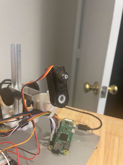
Advice I've gotten from others who have made companion bots is that you need to make it so some of your more common parts, like servos, can be easily replaced. To make sure this was possible I used hot glue to attach the dowel connectors to the servo heads, and mounting putty to place the servos into their slots.
Fill the dowel (wider) end of the dowel connectors with got glue, wiping away any excess from the top and then place your servos into their slots inside the head, push the rod from the outside of the head and then into the dowel connector on the other side, hold until dried. I recommend doing one at a time.
The larger servo that connects to the head can be slide into place and shouldn't require any glue, but you ca use some mounting putty to help ensure the servo never wanders:
I did glue my spine apparatus into place, but make sure you know exactly what you're going to use to attach the head to the body before you do so.
The las step is to connect in the hole cross connector to the larger servo post. This was designed to be a friction fit and should not require glue.
Re-upload the random servo code from earlier in the project to your Uno.