 Otto Gloeckner
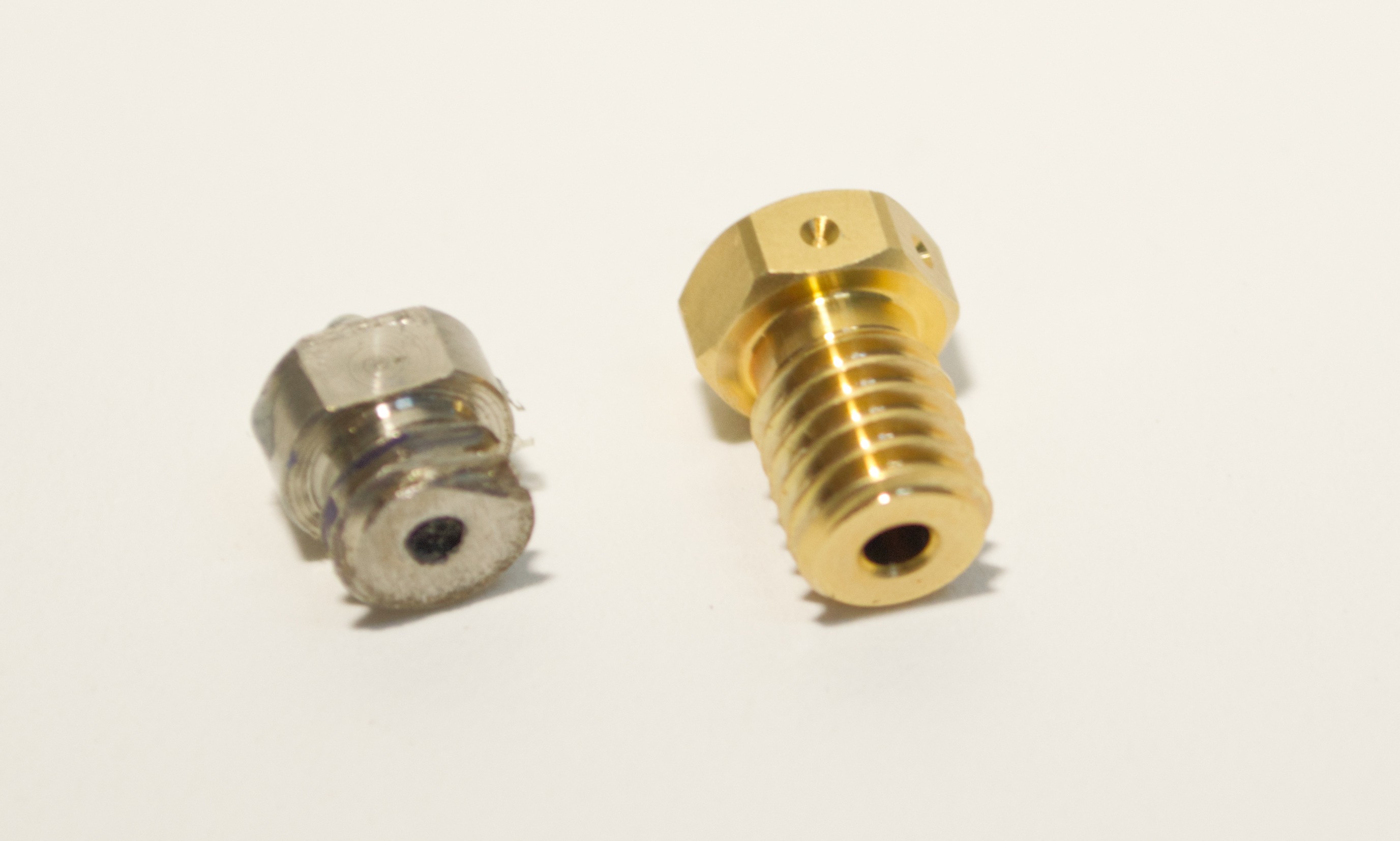
The way a pellet extruder works is that the pellets are pushed into a hot zone where they melt and are then pushed through a nozzle. In injection moulding it is pushed into a mould. In my case, I wanted to make this nozzle a 3D printed one.
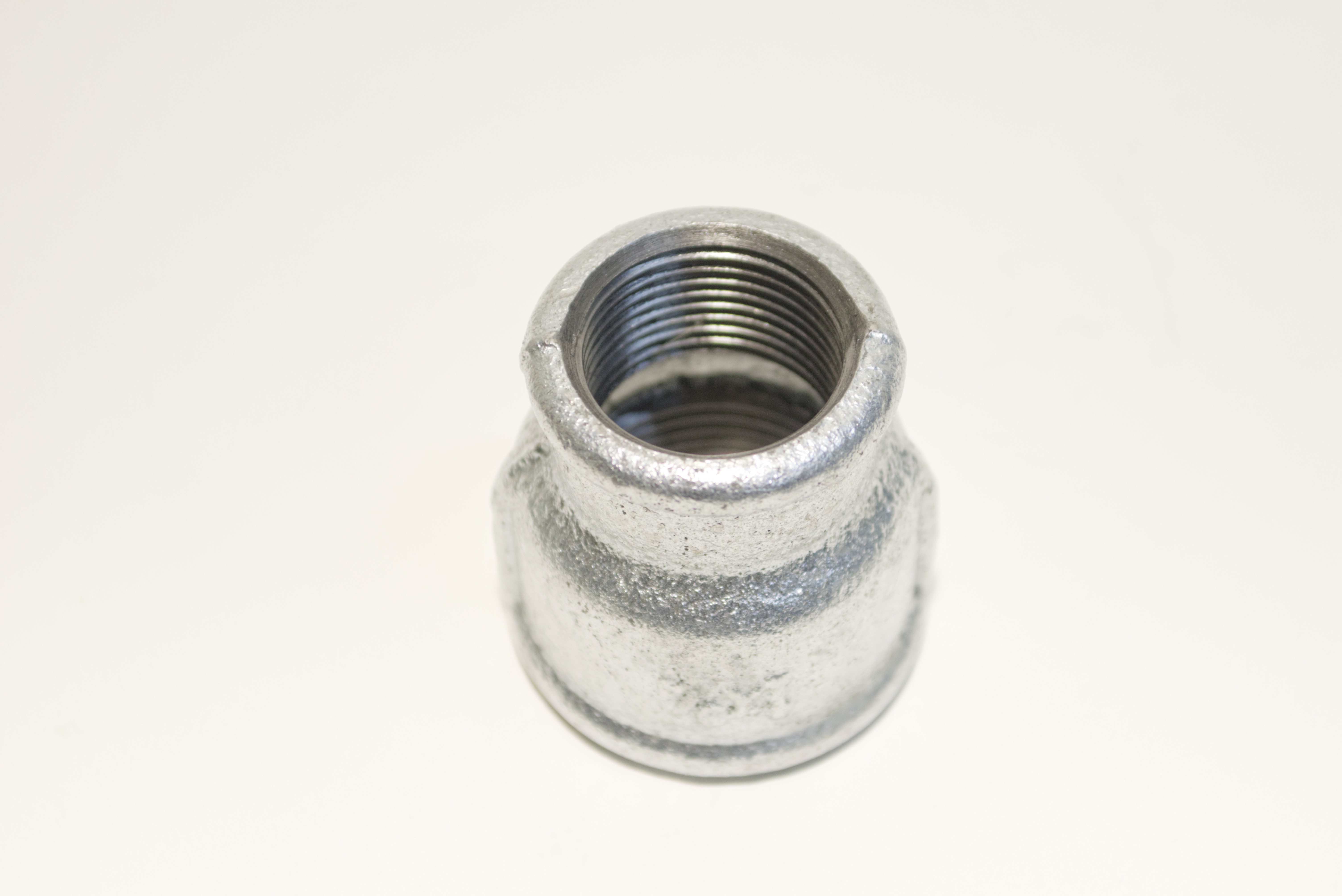
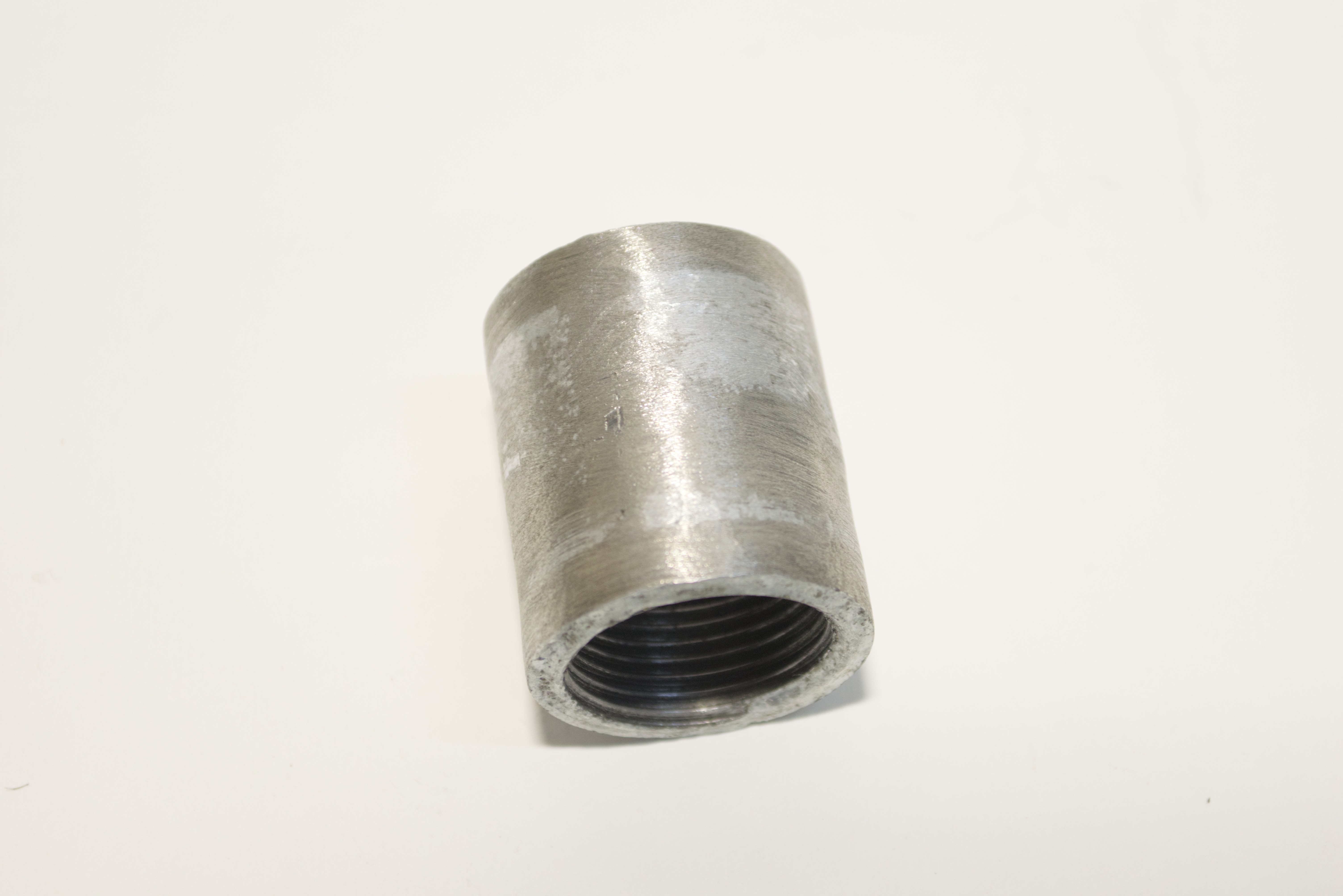
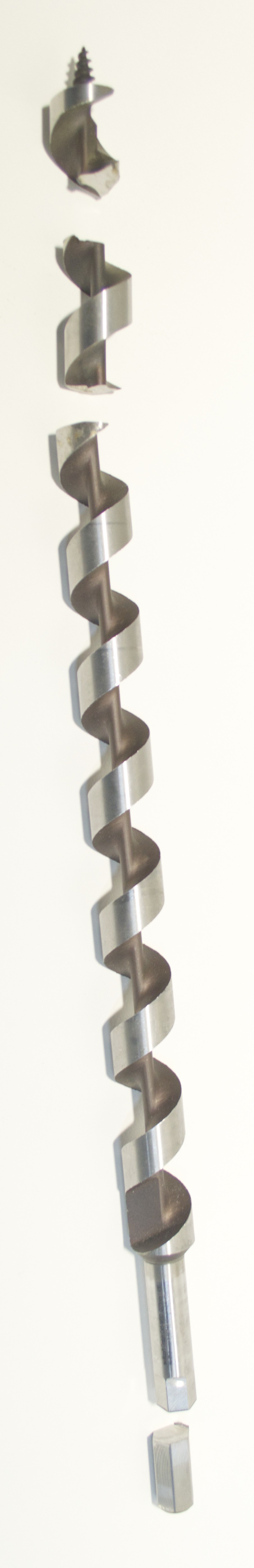
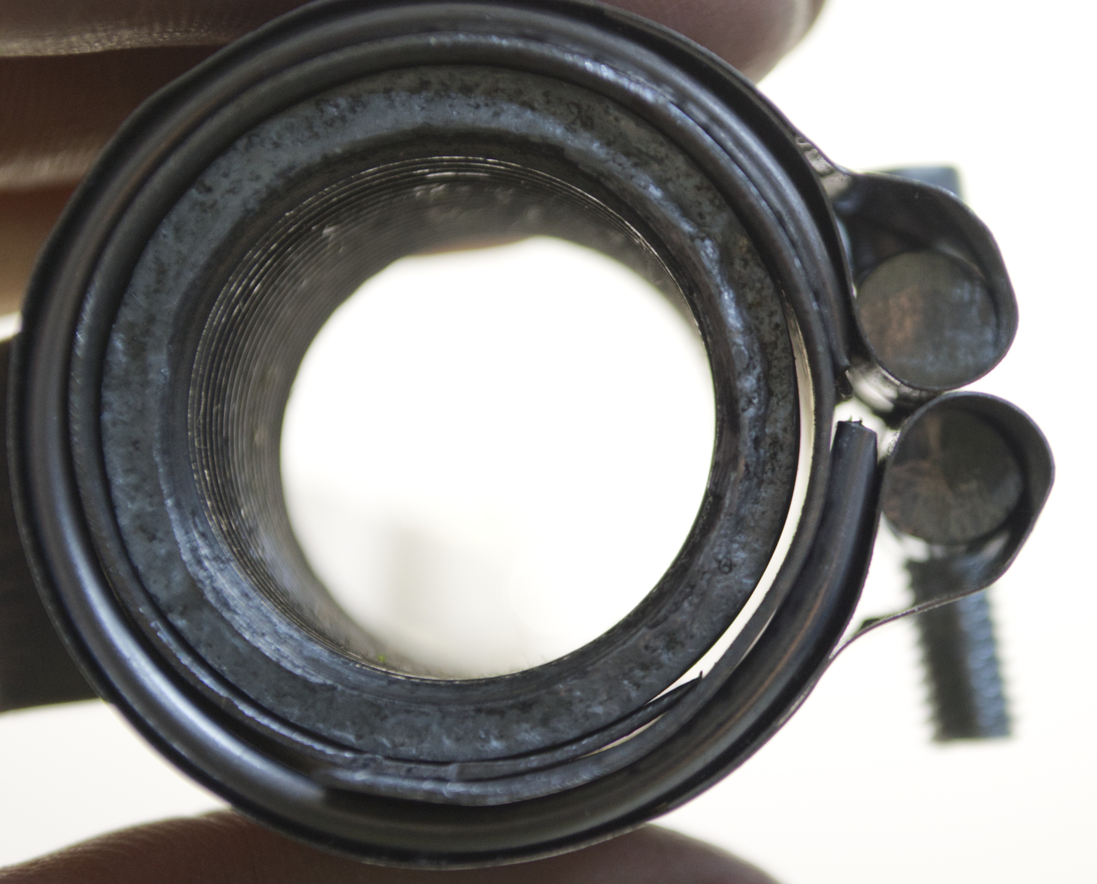
By looking at the work of others. A pipe with a wood drill can work, so I decided to go with that.
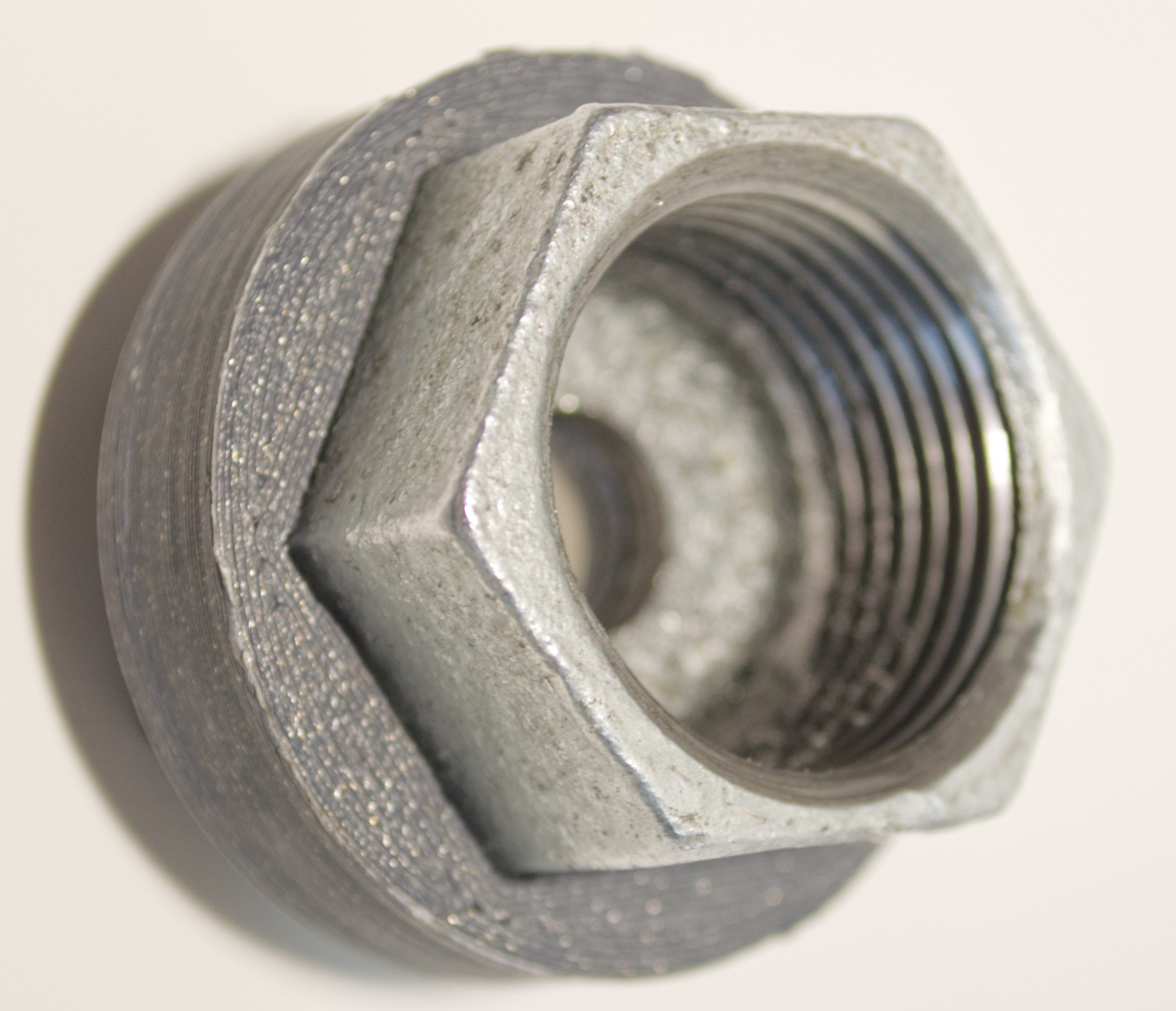
I grabbed some pipes that are normally used for water plumbing and a large auger for wood drilling.


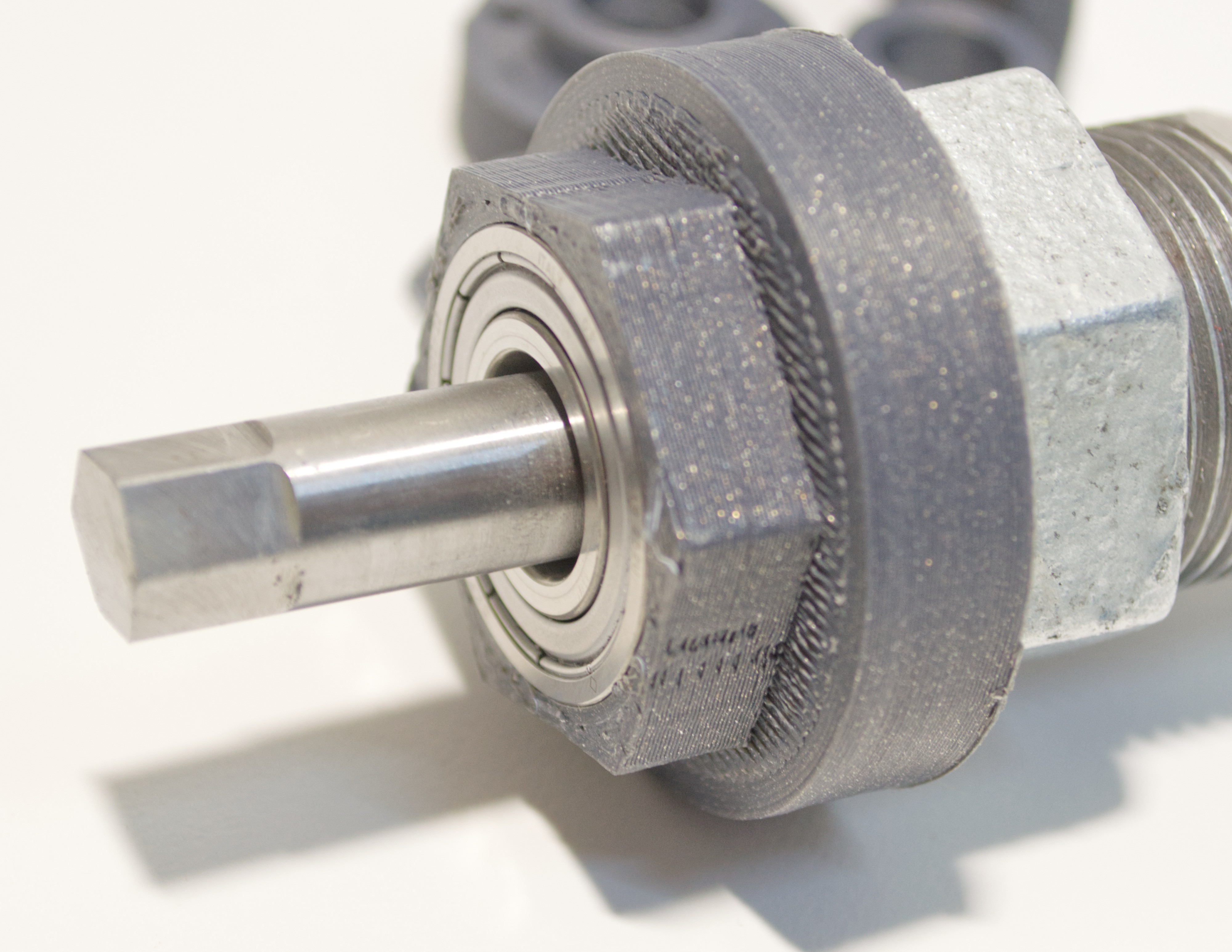
Now I had to figure out how to drive the drill and connect it to my 3D printer.
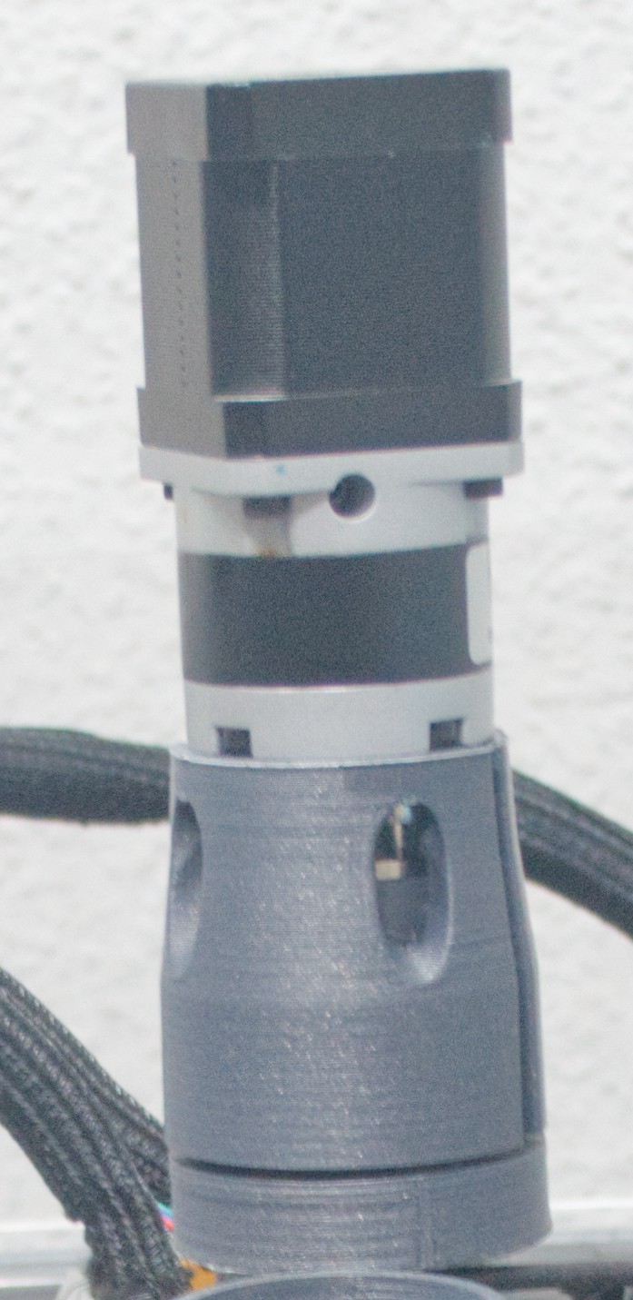
I jumped into CAD (Fusion 360) and designed a 3D print head with part cooling and cooling for the pellet section. The dimensions I chose for the distance to the heated area and the fans were completely subjective. I hadn't designed a machine like this before, so I was a bit worried that the printed parts might deform close to the heated zone.
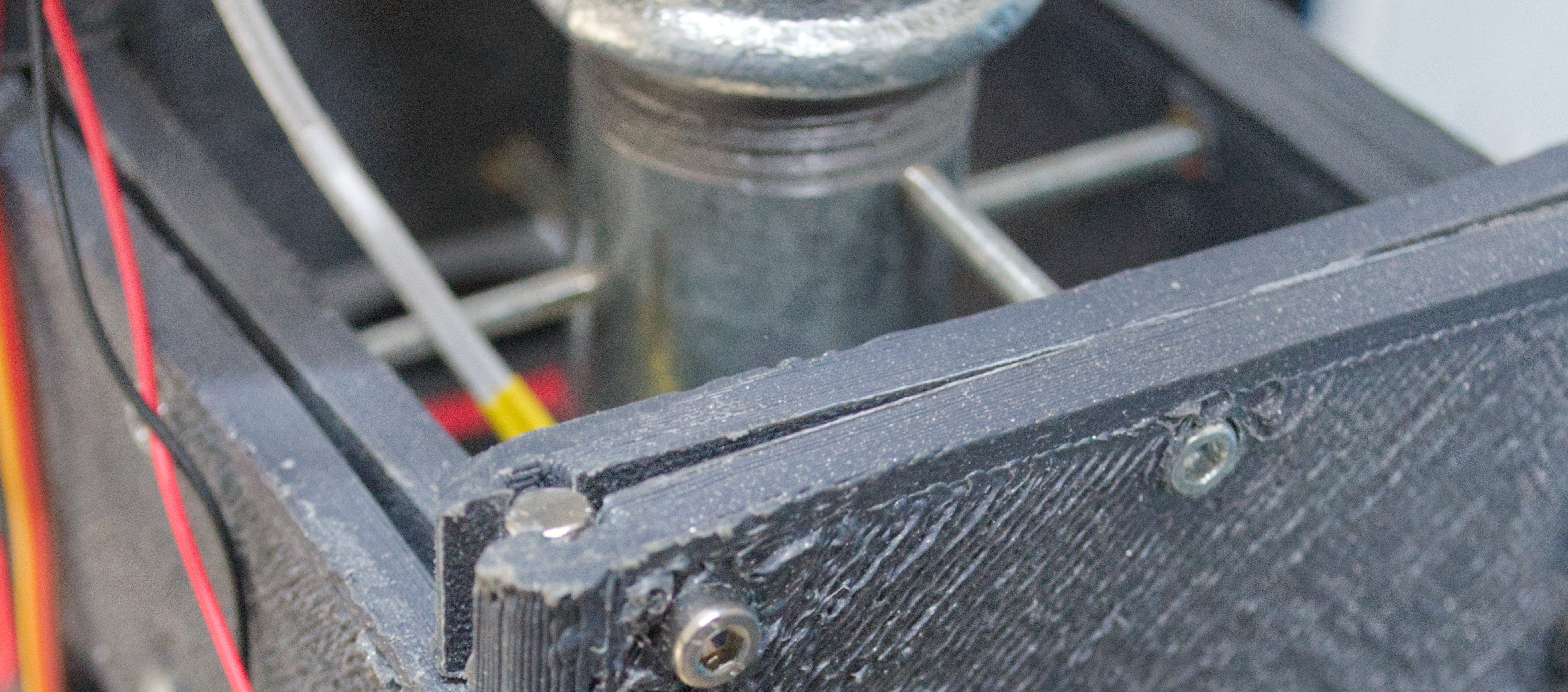
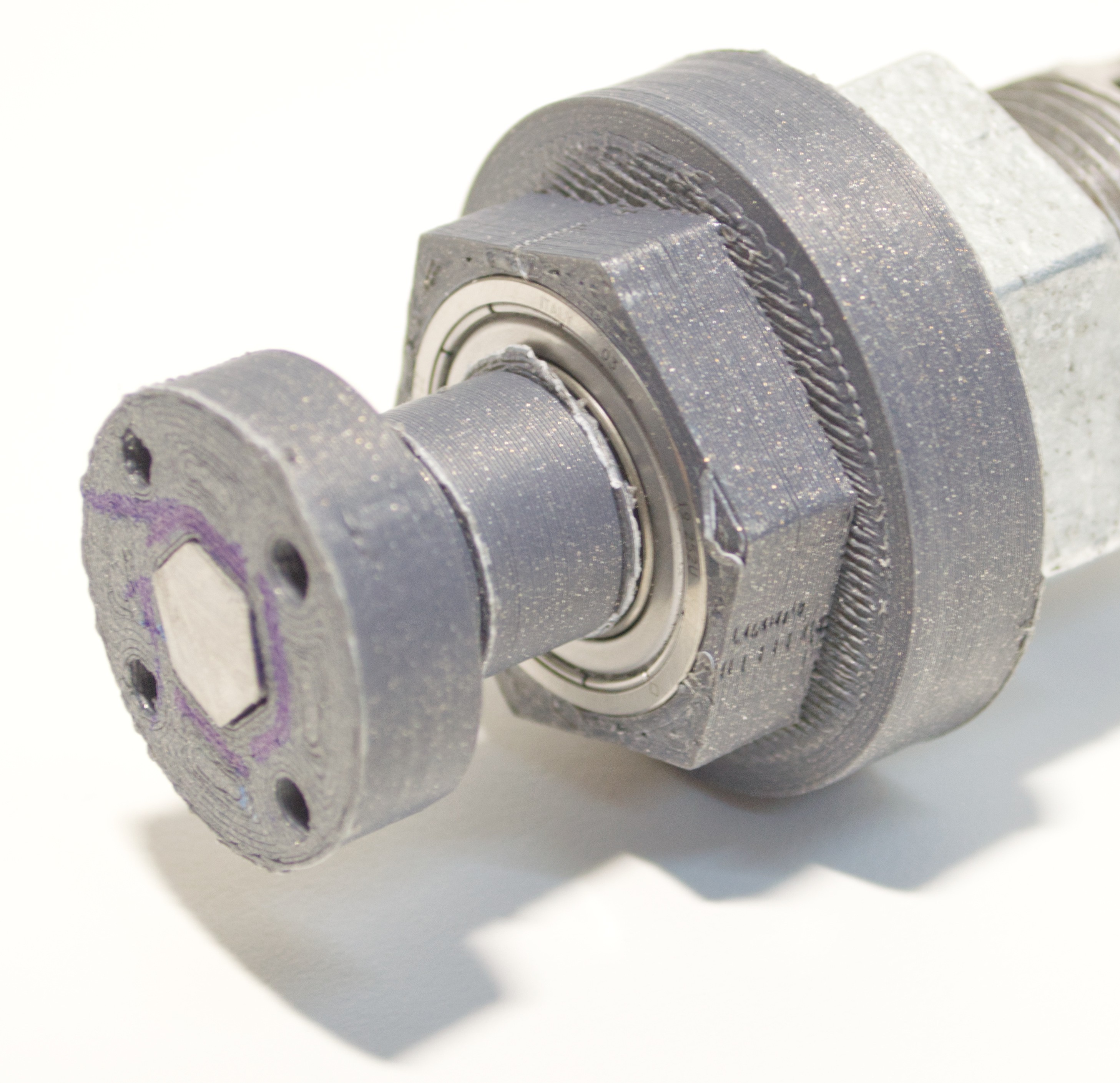
To hold the 3D printed parts, I used a 5mm iron rod that I cut to size. As you can see in the picture, the 3D printed parts act as a sort of clamp to hold on to the rod.
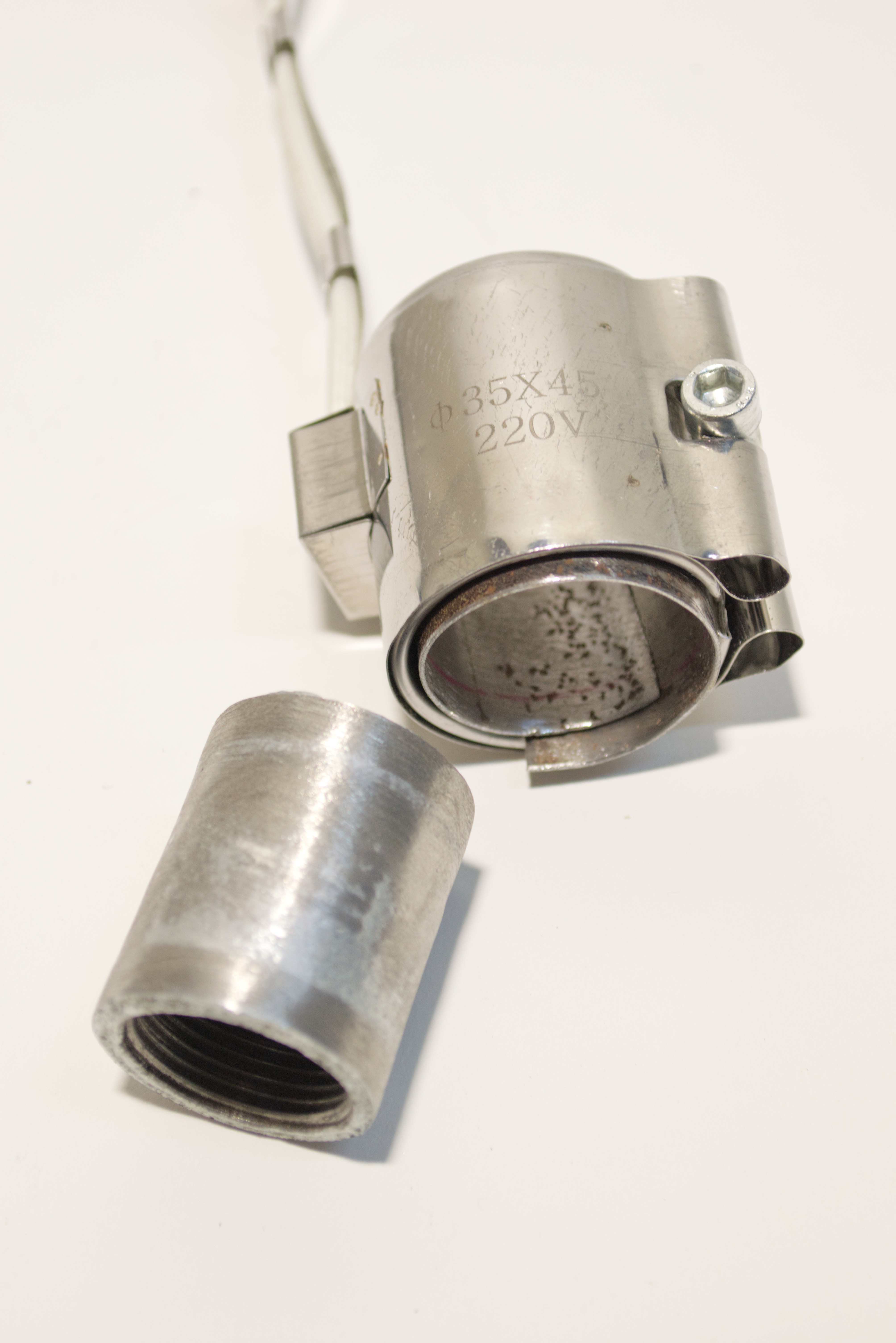
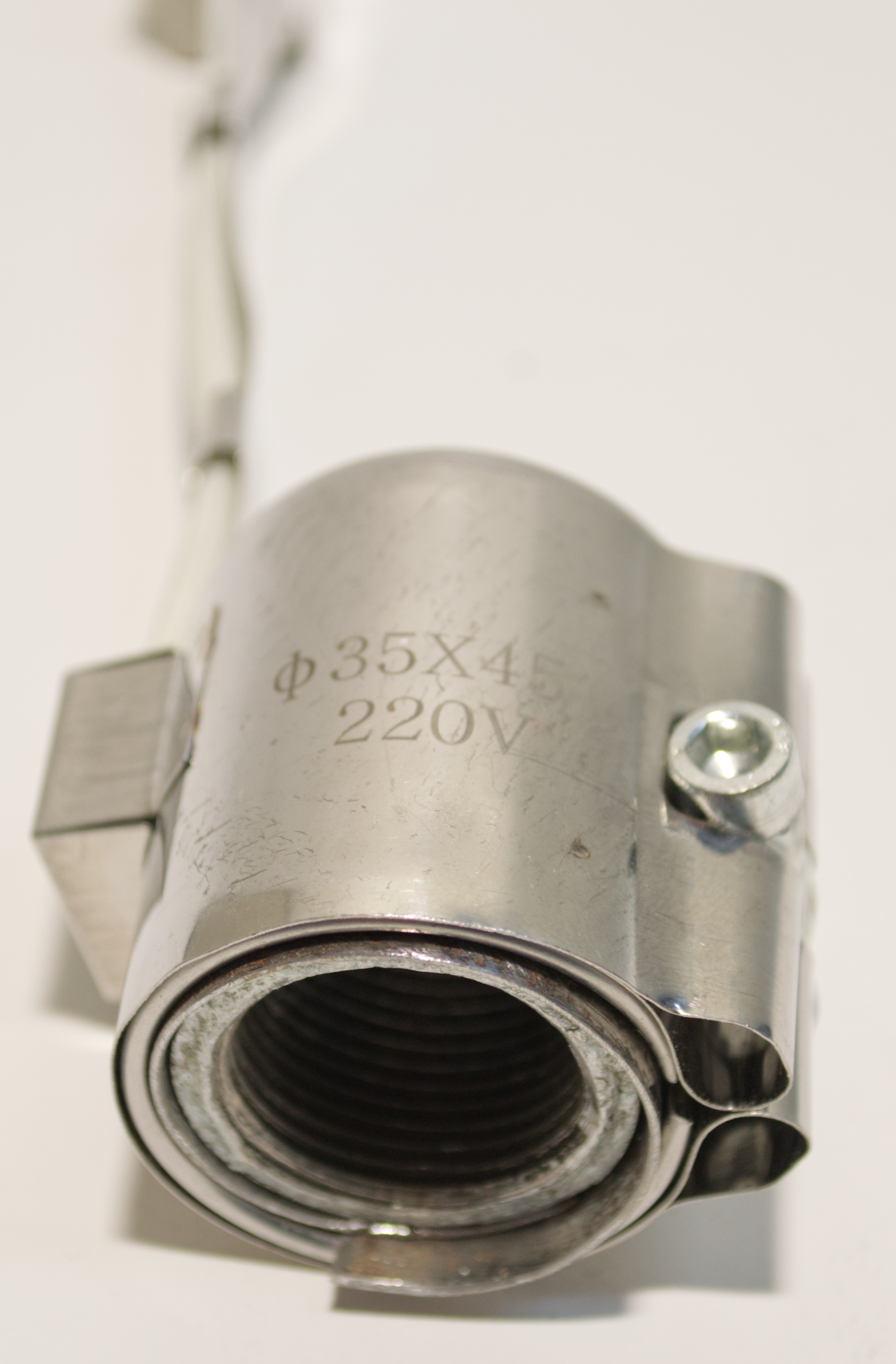
Heating Element
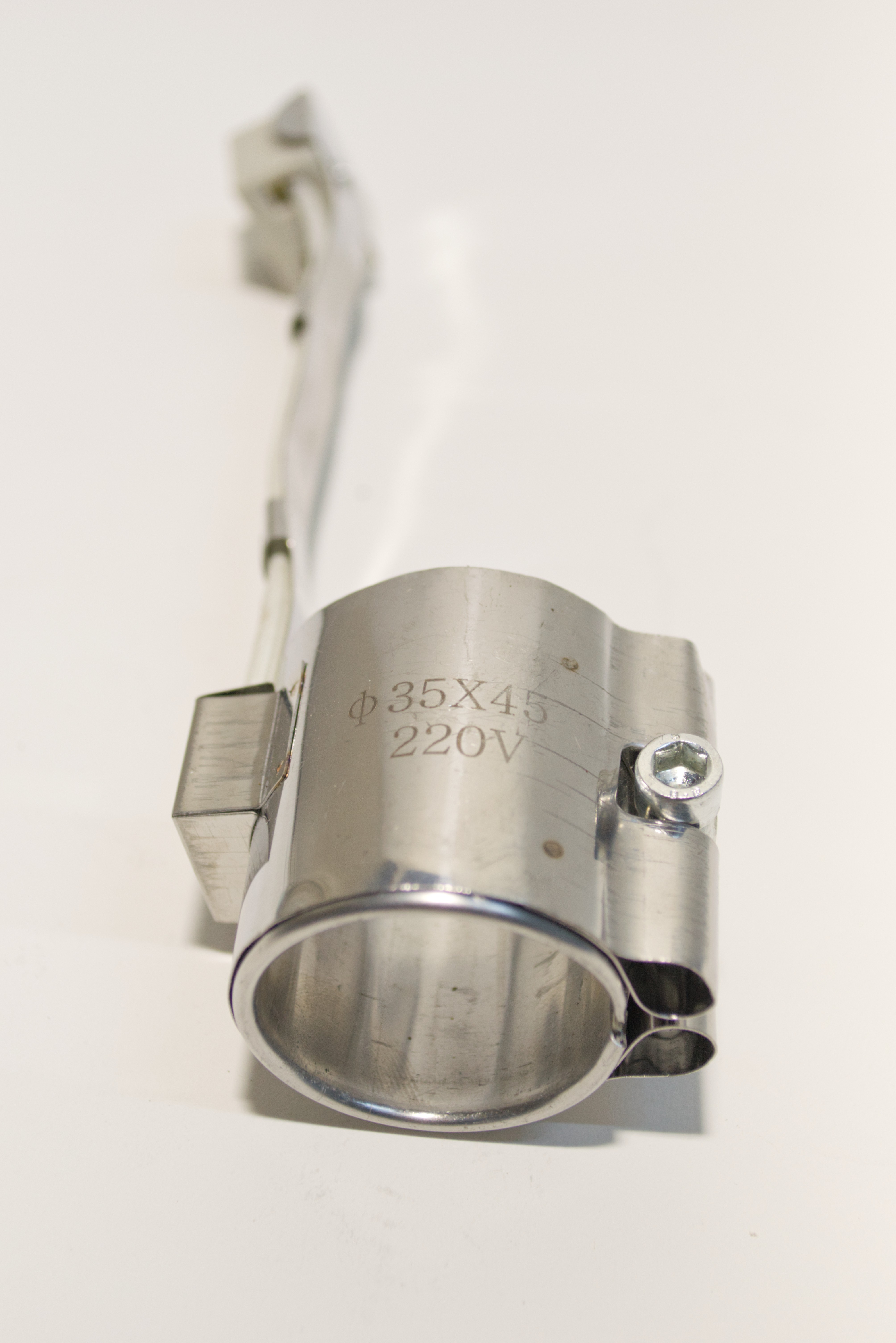
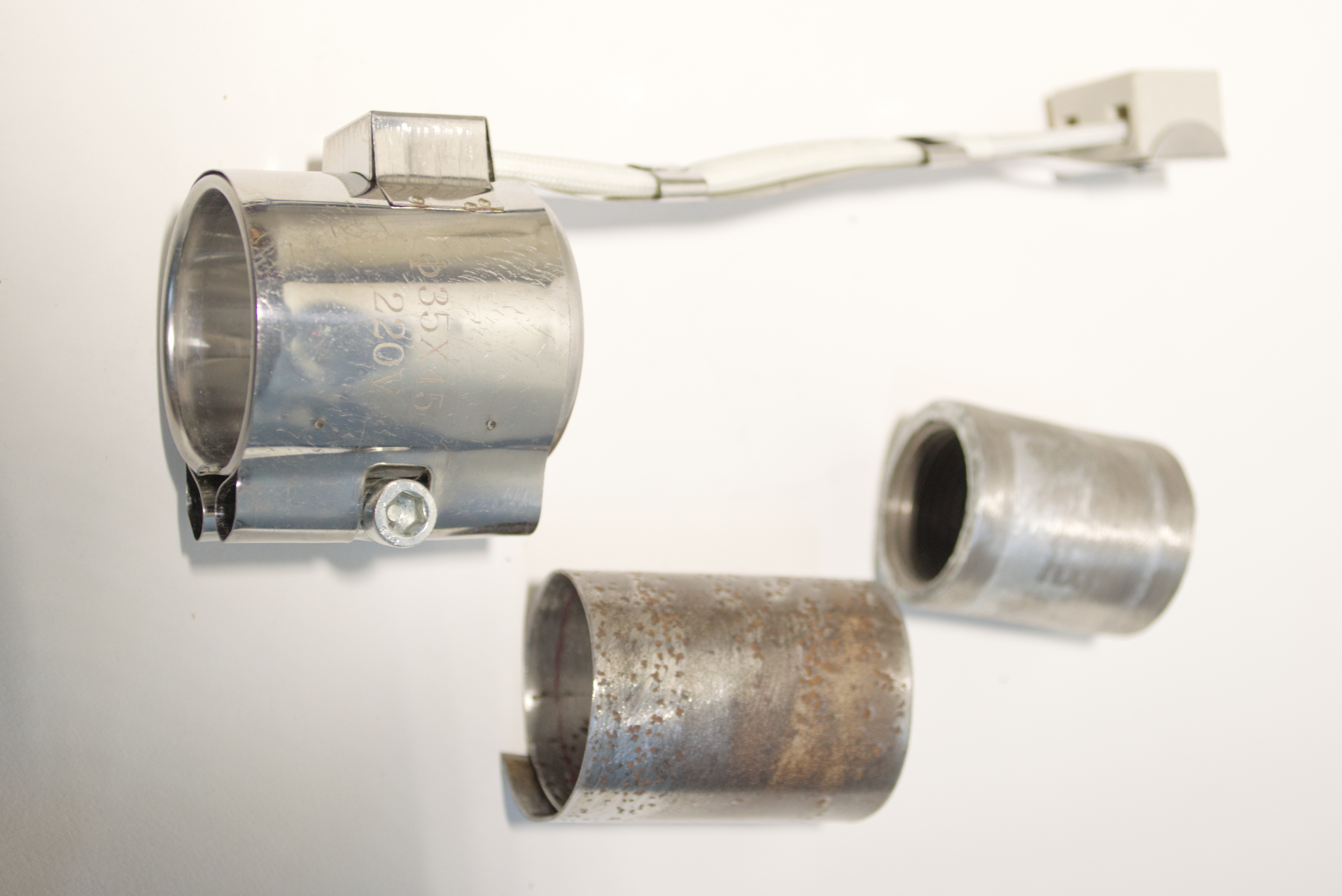
There is a Problem
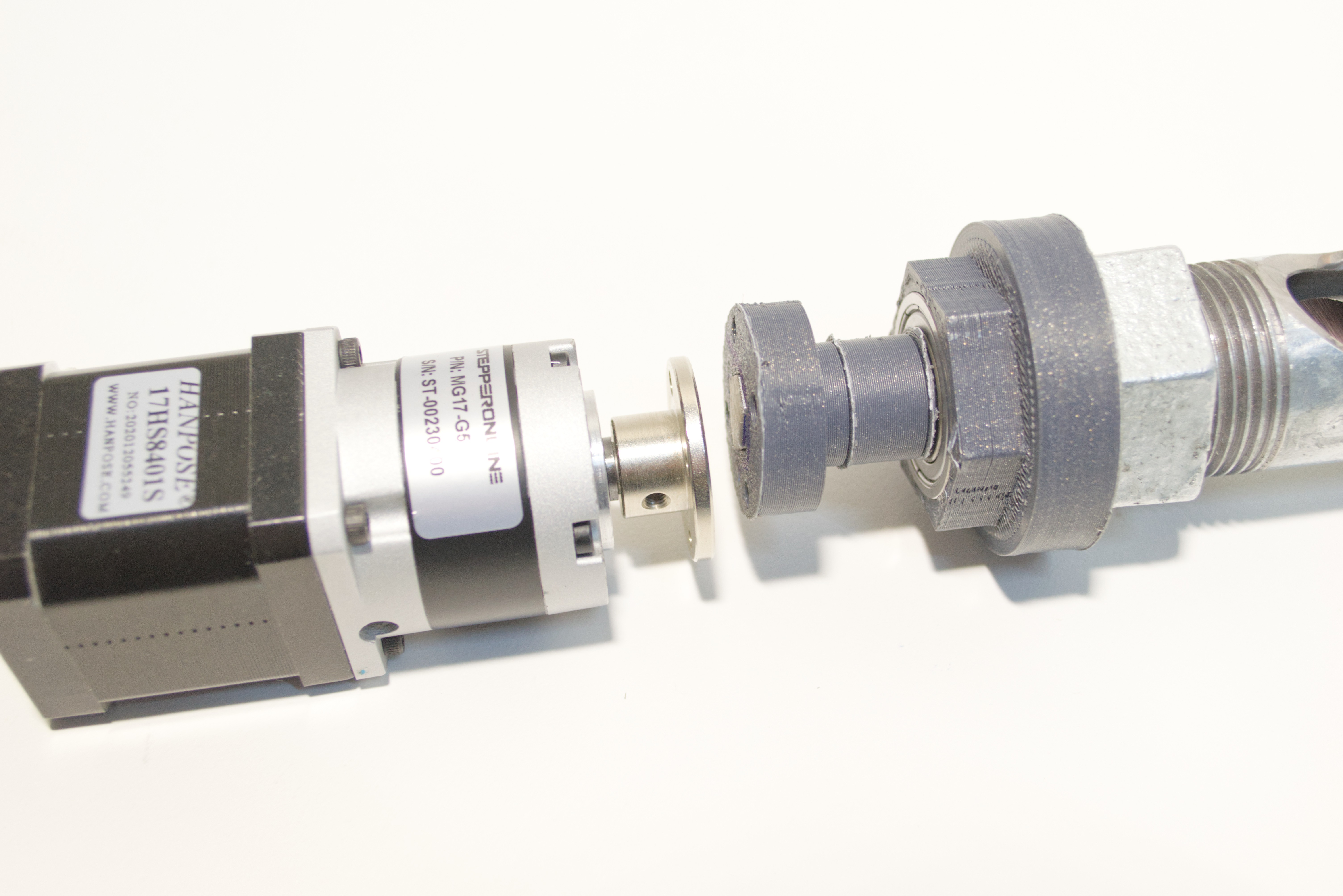
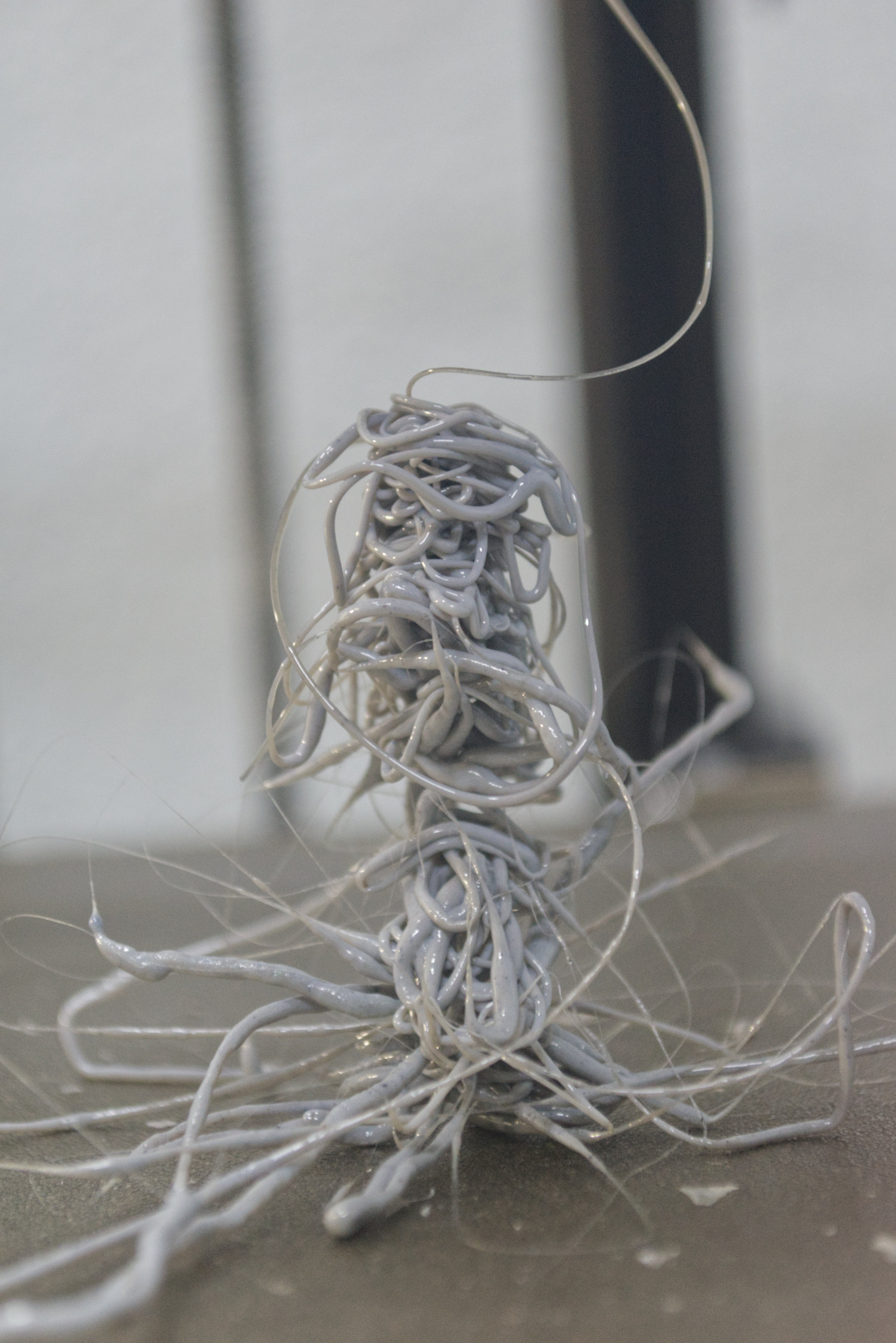
While testing the Extruder I discovered a problem. My Nema17 motor with a 5:1 gearbox was having trouble turning the drill. It seemed that the torque required to turn the drill was too high for my configuration. I then tested the rotation by hand and was able to extrude molten PET plastic that I had previously shredded.
The solution seems to be to improve the power by getting a stronger nema23 motor with a stronger gear box.
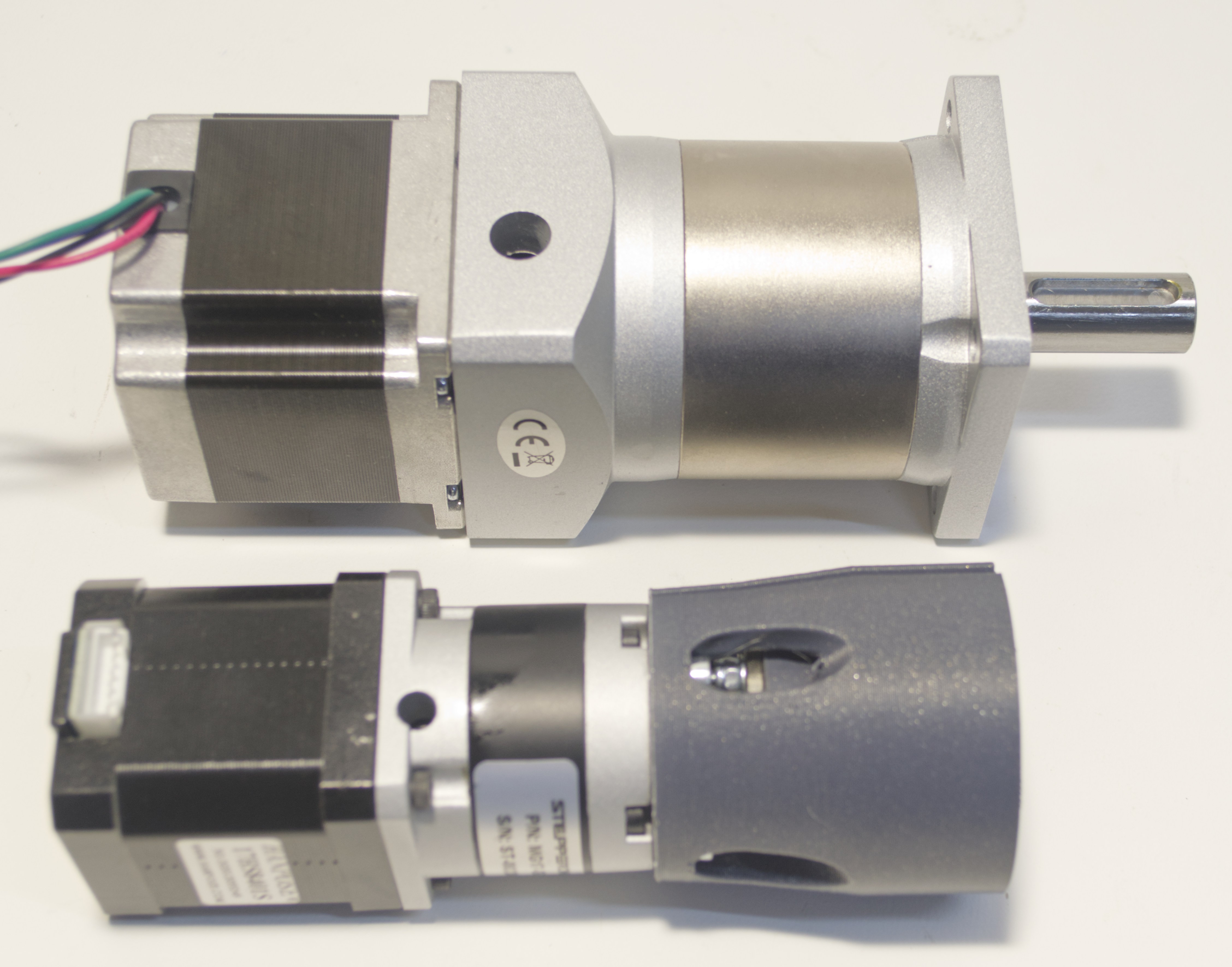
The weight of this Nema23 motor with gearbox is more than double and I do not want to mount it the way I did with the old motor. So I will have to make a design that turns the orientation 180° basically upside down.
Therefore this design is still a work in progress and not fully functional.
I release it under the Creative Commons Zero v1.0 Universal Licence. I invite you to give comments and ideas for future development or to use it in your projects if it is useful.

 Russell Munro
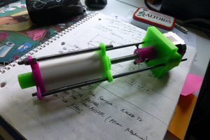
 doctek
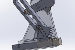
 BogdanTheGeek
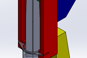
 Dante Kienigiel