I have decided to switch to CircuitPython for creating the device firmware. I initially wanted to use QMK since I had spent a few days learning it to configure the Adafruit Macropad. However, I figured that most of the loafdeck (name WIP) functions won't be keycodes so there isn't a pressing reason for me to use QMK. One QoL improvement is the ability to import local .bmp images directly into bitmap objects, rather than needing to export, convert to byte array, and paste into firmware. This can be done either through the displayio or adafruit_imageload libraries. I've begun trying to teach myself how to make 1-bit pixel art and uploading iterations of the screen art work will be more streamlined now.
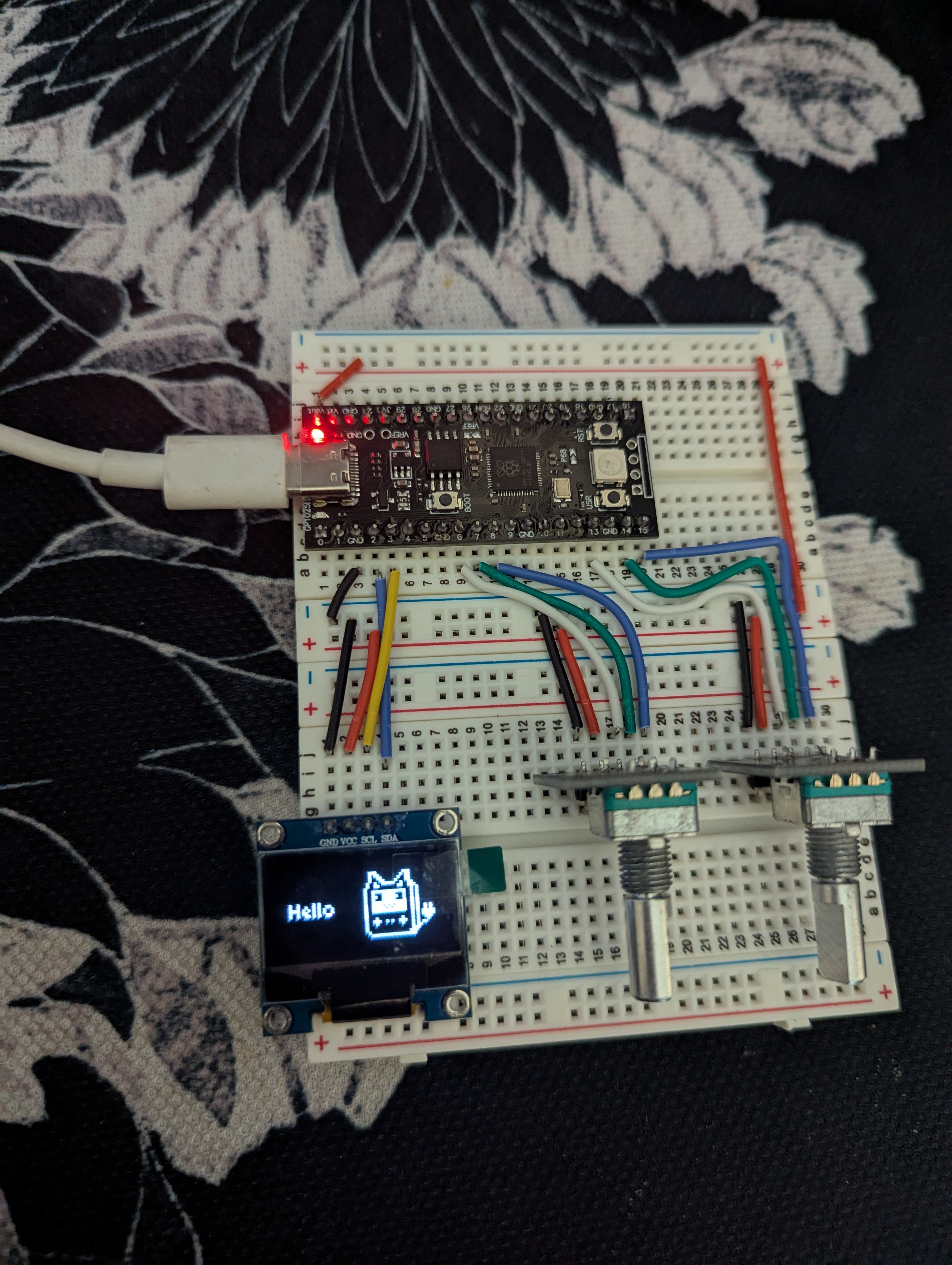
I am using the Adafruit_displayio_ssd1306 library to display images and text. The displayio.TileGrid class is helpful for using sprite sheets, which will reduce the number of image files needed to be uploaded. A sprite sheet of arbitrary size can be uploaded as a "grid," and each grid can be split into "tiles" for easily calling the image you want. As a simple test, I went in GIMP to create an image with twice the height of my oled dimensions, 128x128 in this case. The top 128x64 of the image is one screen state, and the bottom half is a second screen state. I import the bitmap as a 1x2 tile grid, with each tile being the size of the screen. In circuit python, you can easily switch between which tile is being shown on the display. This is a very rudimentary test as grids and tiles can be any size and located anywhere on the screen.
Another good feature of displayio are the palette and pixel_map features, specifically being able to designate specific colors as transparent. This was useful for me as I was trying to create sprites for the left hand and right hand of the screen separately. The sprites I was using took up the whole screen, so the sprites would draw over each other rather than showing something on both halves of the screen. Setting black to transparent allows for this to work, although I may look into having smaller tiles instead.
Serial communication is handled by the usb_cdc library. The rp2040 actually has 2 serial ports available, with one disabled by default. The normally used serial port, identified as usb_cdc.console, is typically used for the REPL. This port would be usable for two way communications, but data can be interrupted and only one program can access the port at a time. I am experimenting with the usb_cdc.data port which is normally disabled, so is unaffected by the REPL data stream. I have gotten the device to output a message to serial if the first encoder is turned one direction. I used PuTTY to confirm the device was sending serial data that could be read.
I am very inexperienced with circuitpython and python in general, but I have attached my test code for reference. I pieced it together by taking from the few examples available and trying to decipher the documentation. I figure for someone with as little knowledge about (circuit)Python as I had 24 hours ago (no knowledge), this example could be helpful for starting projects that require two-way communication and updating a display accordingly.
import board
import rotaryio
import digitalio
from adafruit_hid.keyboard import Keyboard
from adafruit_hid.keycode import Keycode
import usb_hid
import time
import displayio
import busio
from adafruit_displayio_ssd1306 import SSD1306
from adafruit_display_text import label
import terminalio
import usb_cdc
import adafruit_imageload

#create object named 'serial' connected to the unused serial data port
serial = usb_cdc.data

# Release any existing displays
displayio.release_displays()

# Initialize I2C
i2c = busio.I2C(scl=board.GP3, sda=board.GP2)

# Create the display bus
display_bus = displayio.I2CDisplay(i2c, device_address=0x3C)

# Create the SSD1306 display object
display = SSD1306(display_bus, width=128, height=64)

# Create a display group 'splash'
splash = displayio.Group()

#import bmp image named 'tall.bmp' into a bitmap named 'bitmap3' and get palette from image
bitmap3 , palette = adafruit_imageload.load("tall.bmp", bitmap=displayio.Bitmap, palette=displayio.Palette)

#make the black transparent in the palette named 'palette'
palette.make_transparent(0x000000)

#create tile grid named 'tallgrid' using bitmap3. Set tile dimensions to match screen dimensions.
#as tall.bmp was 128x128, tallgrid will be 1 tile wide by 2 tiles tall.
tallgrid = displayio.TileGrid(bitmap3, pixel_shader=palette,tile_width=128,tile_height=64,width=1,height=2)

#append tallgrid to display group 'splash." default tile shown will be tile 0
splash.append(tallgrid)

# Show the group 'splash' on the display
display.root_group = splash

##################################################################################

# Initialize Encoders
encoder1 = rotaryio.IncrementalEncoder(board.GP7, board.GP8)
encoder2 = rotaryio.IncrementalEncoder(board.GP14, board.GP15)
last_position1 = encoder1.position
last_position2 = encoder2.position

# Initialize Encoder buttons
button1 = digitalio.DigitalInOut(board.GP6)
button1.direction = digitalio.Direction.INPUT
button1.pull = digitalio.Pull.UP

button2 = digitalio.DigitalInOut(board.GP13)
button2.direction = digitalio.Direction.INPUT
button2.pull = digitalio.Pull.UP

while True:
    # Read Encoder positions
    position1 = encoder1.position
    position2 = encoder2.position
    position1_change = position1 - last_position1
    position2_change = position2 - last_position2

#if encoder is turned clockwise, set tallgrid to default tile. if ccw, set tallgrid to tile 1.
#encoder cw turn sends message "a ~" through the serial data port.
#
#NOTE: serial.write writes to the usb_cdc.data port that we setup earlier.
#I am using PuTTY to monitor outgoing messages
#print() prints to the usb_cdc.console port, which the REPL uses.
#
#I copy and pasted the tile switching code from an adafruit tutorial, as of right now I dont really know how setting
#tiles works. I believe tallgrid[0] is the default tile, and we are changing which tile is default, and the
#default tile is always shown in group 'splash'. I'm pretty

    if position1 != last_position1:
        print("Encoder 1 Position:", position1)
        if position1_change > 0:
            message = "a ~"
            serial.write(message.encode('utf-8'))
            tallgrid[0]=0
            last_position1 = position1
        if position1_change < 0:
            tallgrid[0]=1
            last_position1 = position1

    if position2 != last_position2:
        print("Encoder 2 Position:", position2)
        last_position2 = position2

    # Read Button 1
    if not button1.value:
        print("Button 1 Pressed")

    if not button2.value:
        print("Button 2 Pressed")
        pass
NOTE: For usb_cdc to work, you will need to add a boot.py file to your device. Mine contains the following:
import usb_cdc
usb_cdc.enable(console=True, data=True)
by default, console is enabled and data is disabled. I was told to NOT disable both interfaces.
I still need to figure out how to draw text dynamically on the screen, for updating volume level and application name. I think once that is done, I just need to figure out a message convention for communicating with the host and all the complicated firmware issues should be sorted out.
I don't really know anything about the serial communication standard, but I am imagining something like the following:
A message "0xxxxxxxxx~." The first character will denote what kind of message is being sent; volume update, application update, or both. The middle of the message can be arbitrarily long and contain either volume level or application name, depending on the first character. The tilde ~ will signify the end of the message.
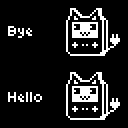
For reference and testing purposes, this is the image I used. I can't upload .bmp files to hackaday so you will need to do that yourself.
For more information about the libraries I mentioned, I recommend looking at Adafruit's guides, looking for other examples, and checking out the documentation. For inspiration on creating 1-bit pixel art, I recommend checking out this project blog by MoonBench. They have uploaded alot of 1 bit concept art designed for the SSD1306. I took the cat gameboy image and the font from that page.
Discussions
Become a Hackaday.io Member
Create an account to leave a comment. Already have an account? Log In.