Real Solar Cars
The Parallax P2 is a very powerful microcontroller, capable of generating 1080p component and VGA video. Unfortunately component and VGA inputs are disappearing from new monitors. The P2 can generate HDMI but maximum of about 330 Mbps falls short of the 750Mbps needed for 1080i.
If we could generate an ATSC signal we could feed that into the RF input on all TVs. The we could use the TV's MPEG decoder as a graphics accelerator. The 4MB required to buffer a full frame full color image would be stored in the TV memory. A big benefit on a microcontroller with 512kB ram. Scrolling could be done with motion vectors.
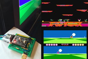
✅ Proof of concept with minimal microcontroller code to determine whether an unfiltered ATSC signal would work.
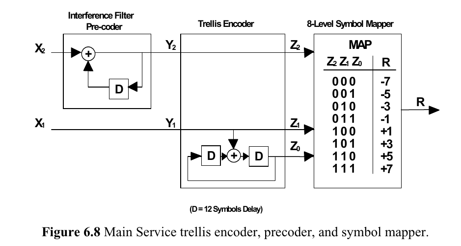
✅ Complete ATSC implementation.
❌ Generating MPEG data on the micro. TBD
❌ Reducing the latency inherent in the TV's MPEG decoder. TBD
❌ Audio. TBD
 rossumur
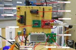
 will.sweatman
 Jac Goudsmit