Now that I've figured out some of the SPI schema I want to make sure I can automatically harvest and display that data with some add-on hardware.
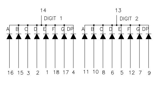
I have measured the logic levels at 3.3V which is perfect for hardware options I have on hand. I grabbed my trusty ATmega168 which I use for a lot of prototyping. It will run on 3.3V and has hardware SPI which can operate in slave mode and has plenty of IO to hook up a two digit 7-segment display (6940HR).

Firmware Description:
SPI packets are sent out by the elliptical machine every 100ms with a clock rate of 125kHz. The packets are 16 bytes (plus one extra bit but I'm really just ignoring that).
Follow along in main.c code. This is from tagged snapshot (prototype1).
I'm using a hardware interrupt to received each byte but it's important to make sure we know where each packet begins. Because of this, my interrupt sets a flag when it begins to receive data. My main loop watches for this flag and checks for the Chip Select to go high, signaling the end of a packet. The two of these allow the main loop to know when transmission has ended at which point the interrupts are disabled and the received data is processed. Here's the general flow of the program:
- SPI transmission starts. The interrupt service routine clears the flag (SShighFlag = 0) and begins filling an array with the data, incrementing an index as it goes. If that index overflows the first item in the array is set to 0x00 and transmission continues.
- The main loop watches for the SShighFlag to be zero an for the SS pin to go high again. These two will indicate the packet transmission has finished
- Global interrupts are disabled while we process data (transmission happen every 10ms so missing some will not matter
- Received data must start with 0xA0, if no there has been a problem (like buffer overflow described above) and the packet is ignored
- The validated packet is processed, display updated, SShighFlag is set, and global interrupts enabled once more to watch for the next packet
The segment decoding in this prototype firmware is extreme. The display has a finite number of states (0-9 and the letter P for 7-segment displays) to a lookup table should be used for subsequent versions of the firmware.
Here's the prototype connected to the elliptical machine. With this proof of concept I can not take the time to reverse engineer the rest of the SPI scheme and then begin work on the final hardware.
7-segment Display Pin Connections:
For verbosity of documentation, here are the connections for this set setup (I'm not planning to make a schematic of this setup):

- Pin 1 -- PD1
- Pin 2 -- PD2
- Pin 3 -- PD3
- Pin 4 -- NC
- Pin 5 -- PD4
- Pin 6 -- PB6
- Pin 7 -- PB7
- Pin 8 -- PD5
- Pin 9 -- NC
- Pin 10 -- PD6
- Pin 11 -- PD7
- Pin 12 -- PB0
- Pin 13 -- GND
- Pin 14 -- GND
- Pin 15 -- PB1
- Pin 16 -- PC0
- Pin 17 -- PC1
- Pin 18 -- PC2
SPI connections:
- GND -- GND
- CS -- PB2
- WR -- PB5
- DATA -- PB3
 Mike Szczys
Discussions
Become a Hackaday.io Member
Create an account to leave a comment. Already have an account? Log In.