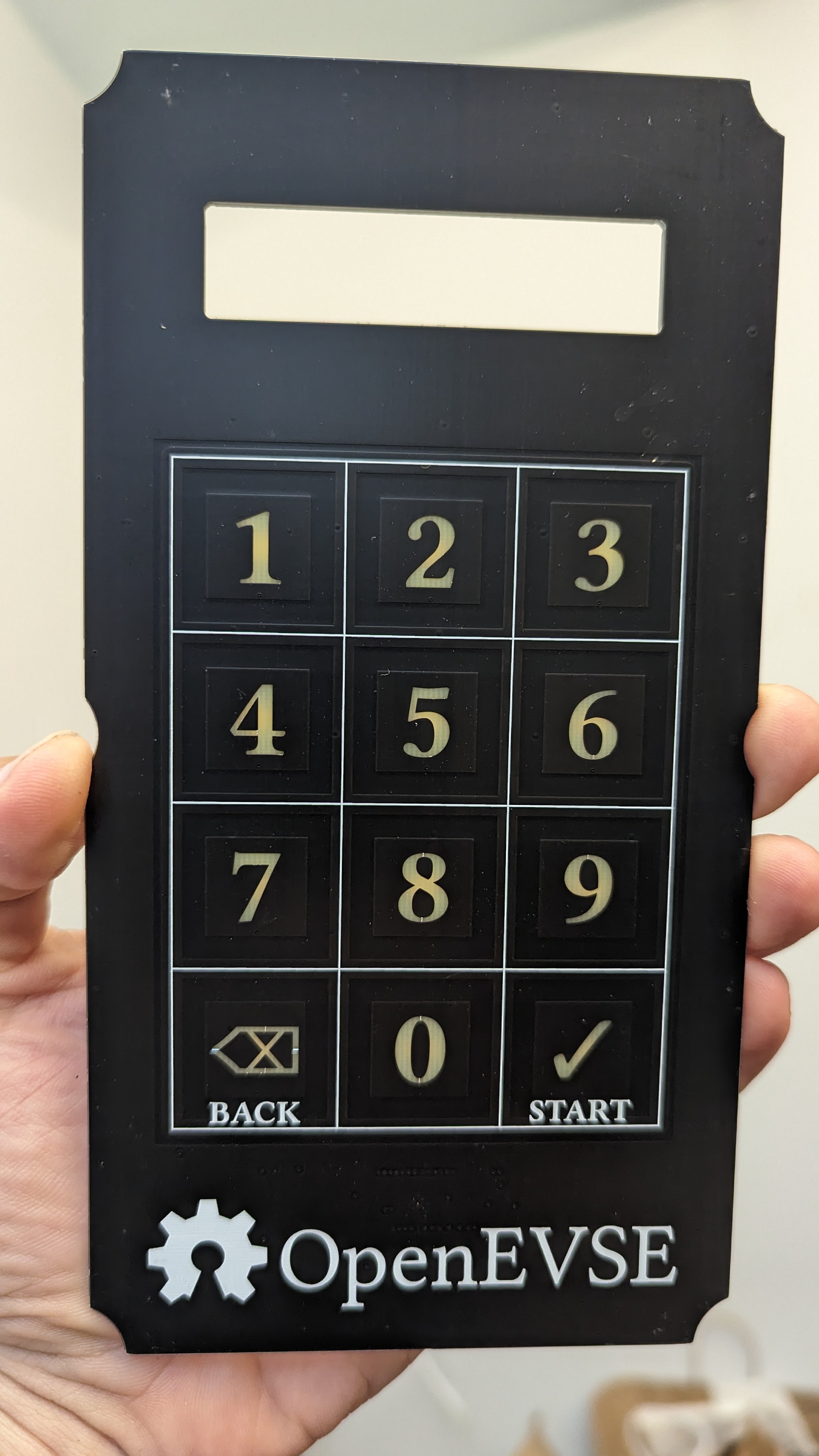
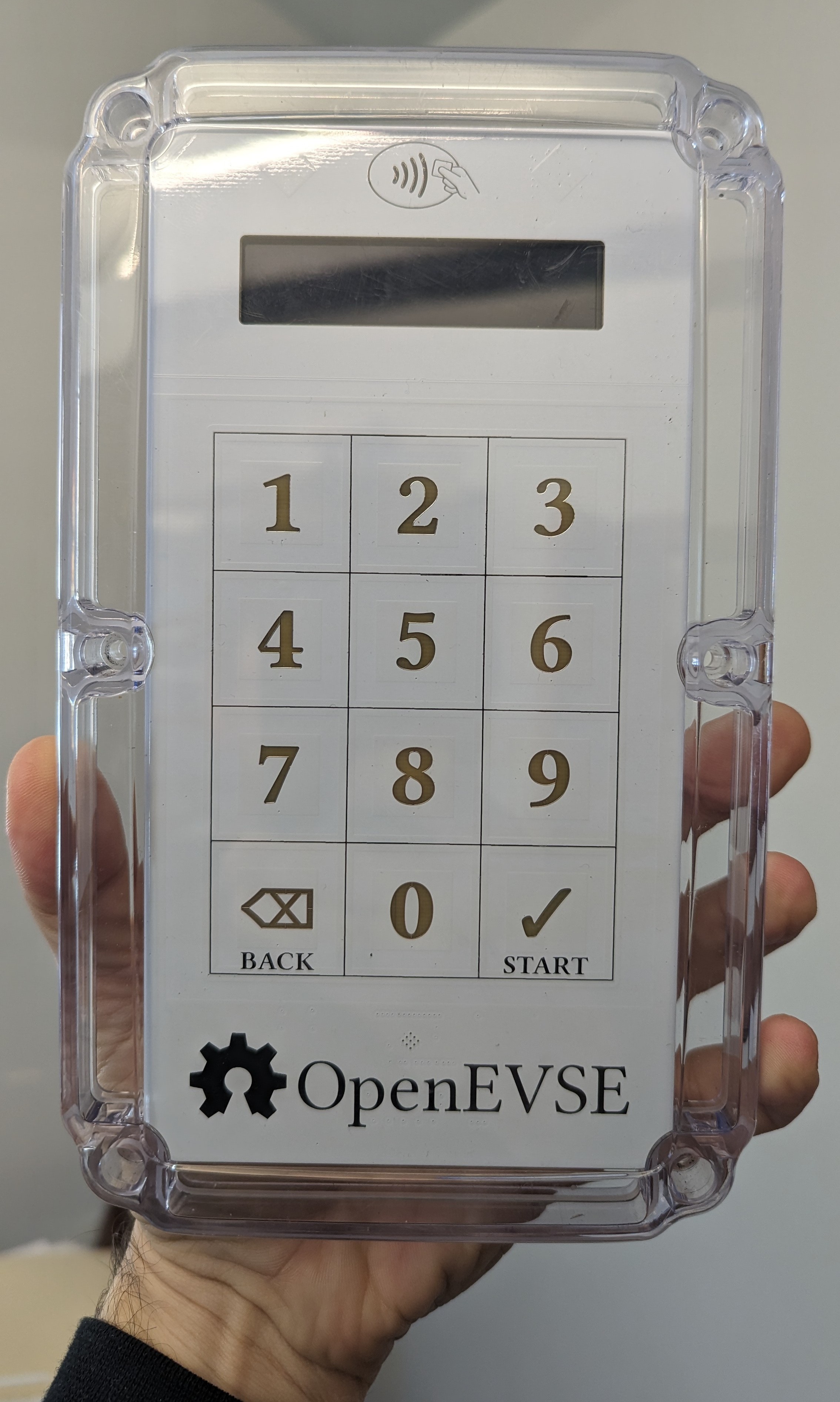
The OpenEVSE hardware ships with a custom-printed front cover for the Polycase ML-58 enclosure. The key idea here was to replace this with the "stock" clear cover, and use a printed PCB for the graphics, integrating capacitive touch as well to avoid any opening which could compromise the weather-tightness of the case. The keypad is backlight by reverse-gullwing LEDs shining through the PCB from the backside.
 |
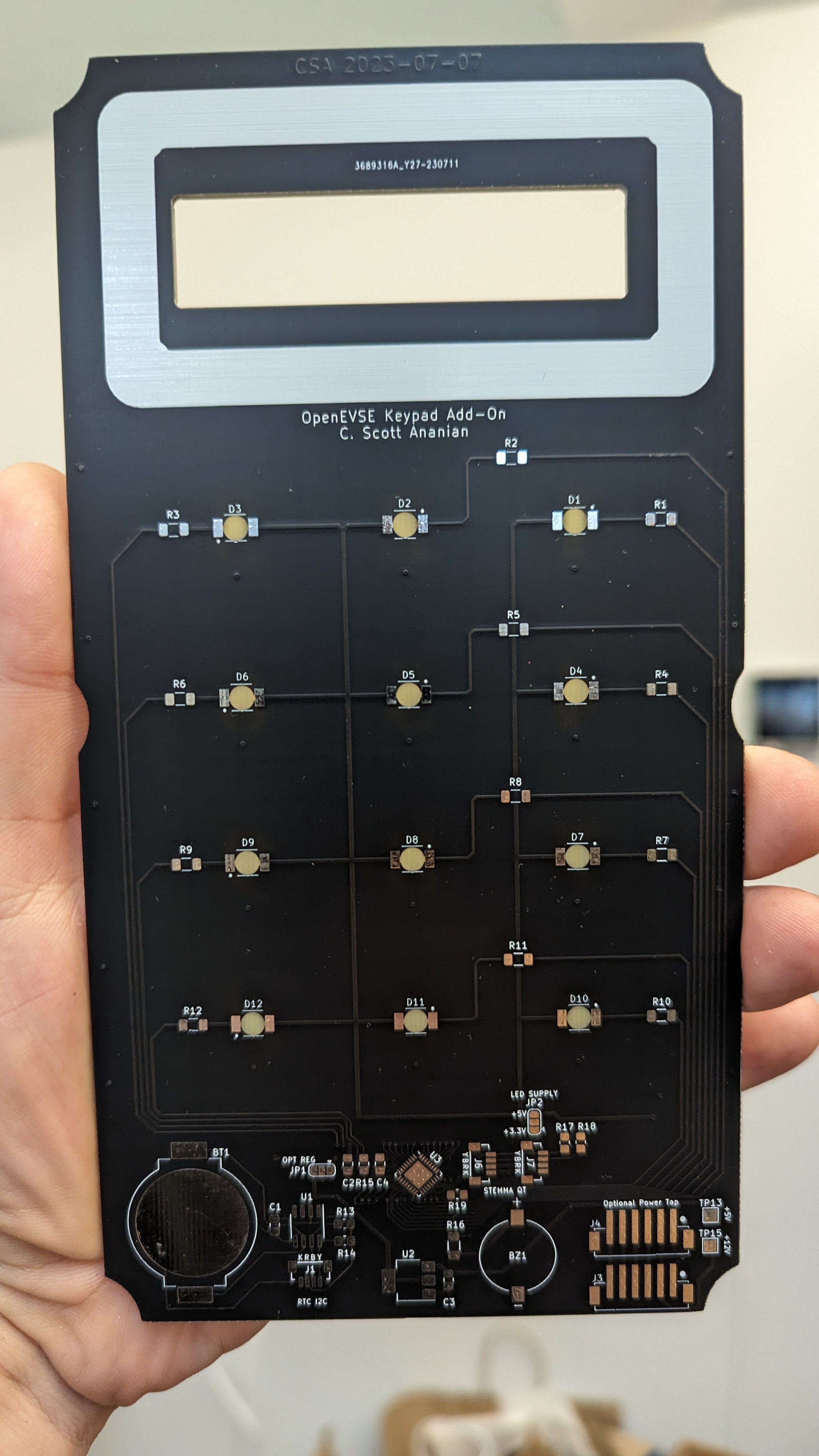 |
Revision 1 of the PCB used a matte black soldermask. It looked good, but I was concerned it would add heat in direct sunlight and limit the power available for charging, since the OpenEVSE hardware carefully limits the temperature of the charger. I also had the idea to add an RFID loop around the display, which motivated revision 2. Revision 1 also needed a series capacitor on the trace for the proximity sensor to bring it within the range of capacitance handled by the CAP1214, and I'd tied RESET high when it wanted to be tied low.
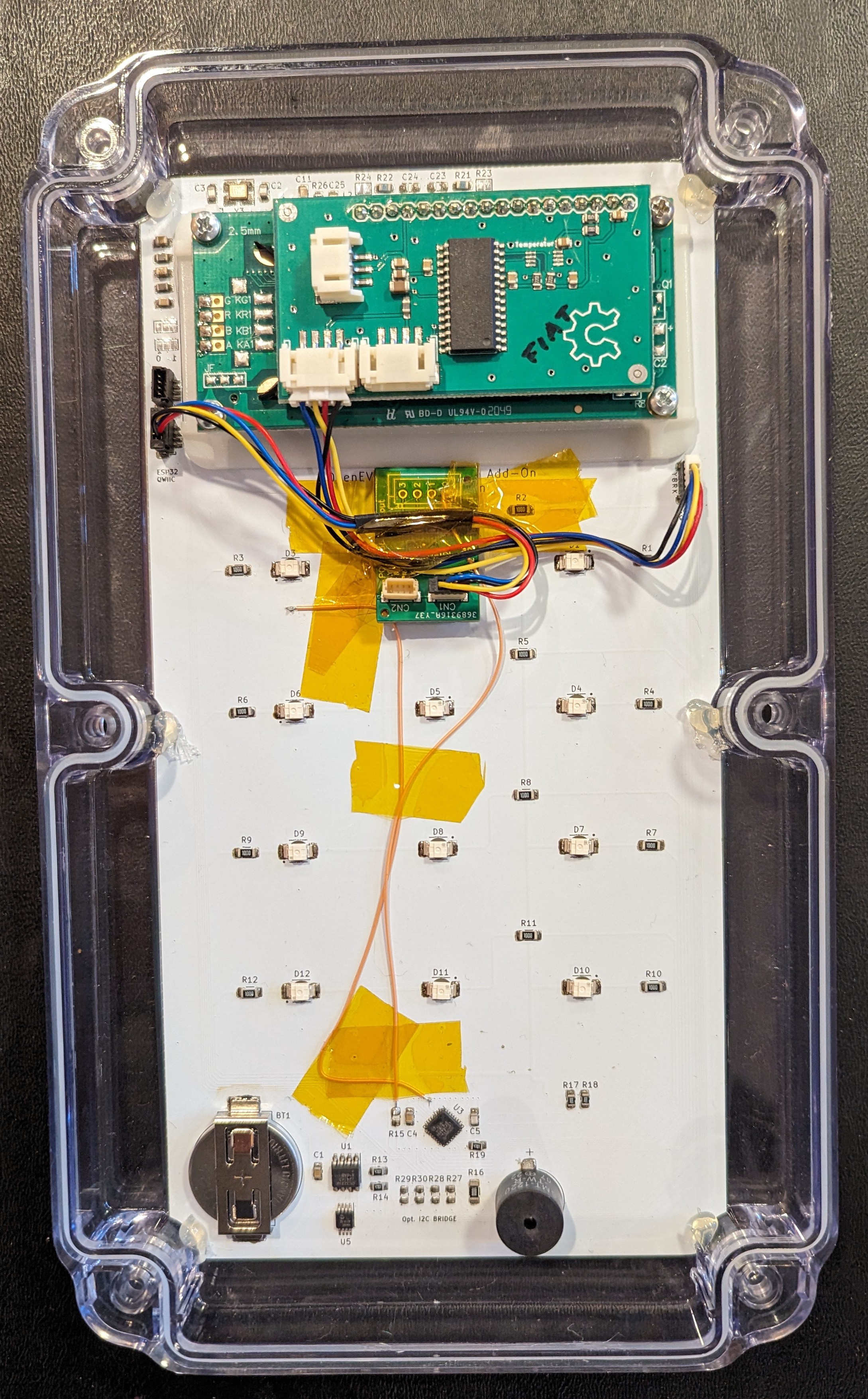
Revision 2 is pictured above, with white soldermask this time, and an RFID logo above the display. It integrates an PN532 RFID reader, and drops some of the CYA features I'd included in the first board, since they basic design and been tested and validated by now. Among these was the idea I'd originally had to backlight the numbers with *ultraviolet* LEDs, since I'd been told that the glow of FR4 under blacklight was pretty cool. In the end I was unimpressed by the look, and the ultraviolet LEDs were a nightmare to source. (In fact, "revision 0" of the PCB actually had two separate boards separated by spacers in an attempt to use forward-shining UV LEDs since the reverse-shining ones were so hard to find; this idea didn't get past the "quote the price of two separate PCBs" stage.) I also moved some of the connector locations around to make wire runs shorter: the other two OpenEVSE boards this interfaces with are mounted at the top of the enclosure, and for whatever reason I'd put all the connectors in revision 1 at the very bottom of the PCB.
 |
 |
This revision works like a charm, and I've got three of them running at my house now -- two for our personal EVs (a model Y and a Fiat 500e) and one more for public use. We can give out PINs for the public charger when we're contacted via PlugShare, or for neighbors who need a place to charge, which lets us track usage.
This revision still has two bodges -- the CAP1214 chip I'm using for the capacitive keypad has only 11 LED outputs, whereas there are twelve keys on the keypad. I hacked around this in v1 and v2 by wiring the "back" and "enter" keys LEDs in parallel, so both LEDs blinked when you pressed either of them. I eventually got tired of the bodge and found a super cheap I/O expander (the PCA9536) which let me add "just one more" LED output to allow driving the two backlights separately. It also had 3 extra GPIOs which I used as inputs to allow differentiating the different hardware revisions. So if/when I make a revision 3, I can include the PCA9536 with a different power-up state on the three "unused" inputs to allow me to determine in software that I'm running on v3, in case pin assignments change or other features get added. The second bodge is the more usual "dumb mistake" kind, where I'd managed to short two traces in the PCB layout in a way that the DRC didn't catch; hence the "green" (actually orange) wire running from U3 to the capacitive pad for key "3". Alas.
So this project is "complete" in the sense that it's working for me, with these bodges, but if other folks are interested in this design I should rev the board one more time and (a) fix the trace and (b) integrate the PCA9536 I/O expander on the main board. The RFID circuit probably could use some Adafruit-style tuning as well, although that only...
 C. Scott Ananian
 Arnov Sharma
 Fabrizio