 sky-guided
I'll put the cool part right up top: it works.
 (and i blew up zero mosfets in the process!)
Version 0.2 boards arrived lookin' nice and spiffy.
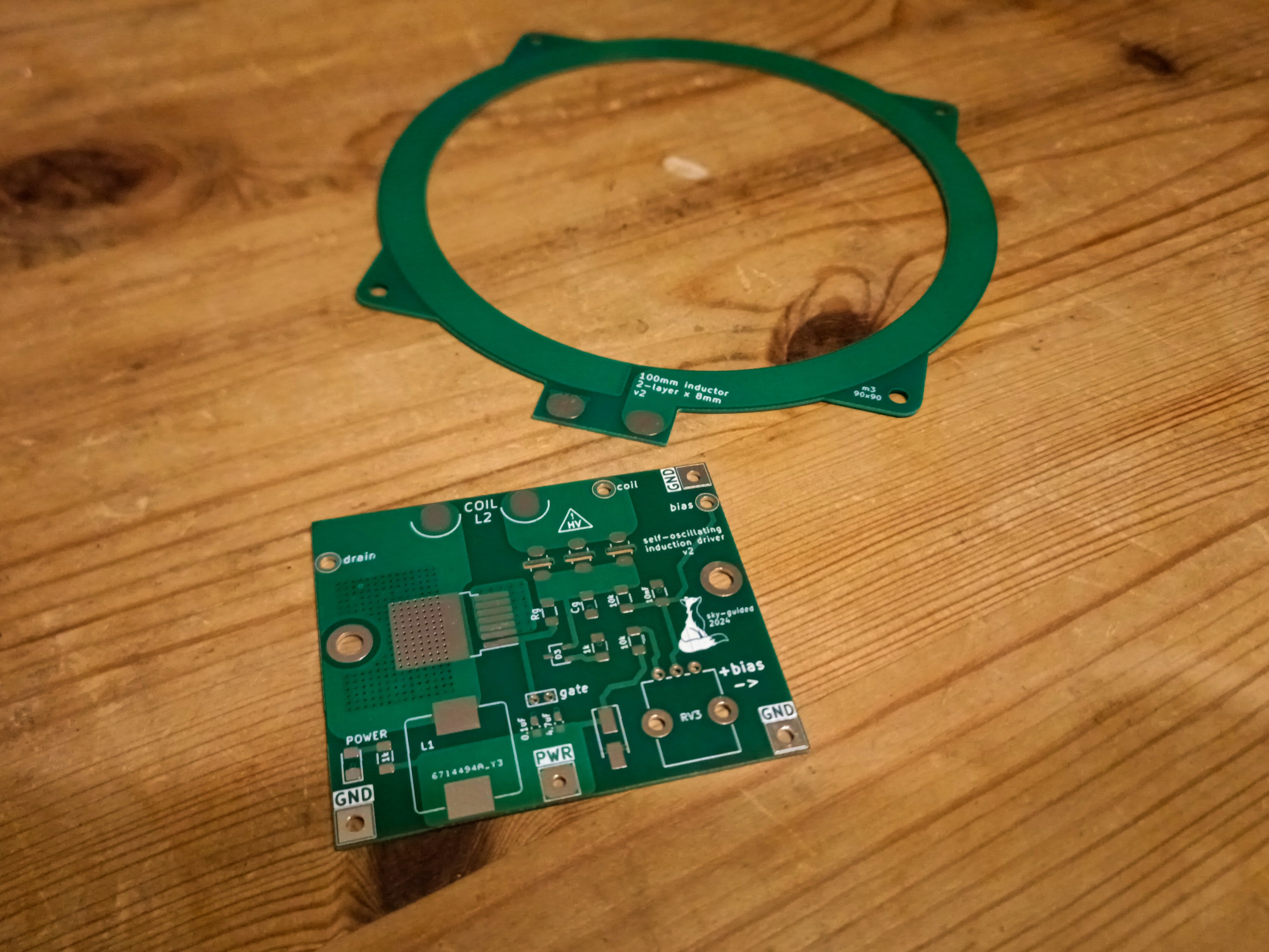
Everyone else I've seen who does a variant on this project uses a primary inductor made either of regular wire or copper tubing. I thought a PCB inductor would be more elegant. This inductor is two stacked turns on 0.6mm PCB, 100mm center span and 8mm wide. I measured the inductance to be about 1.9µH.
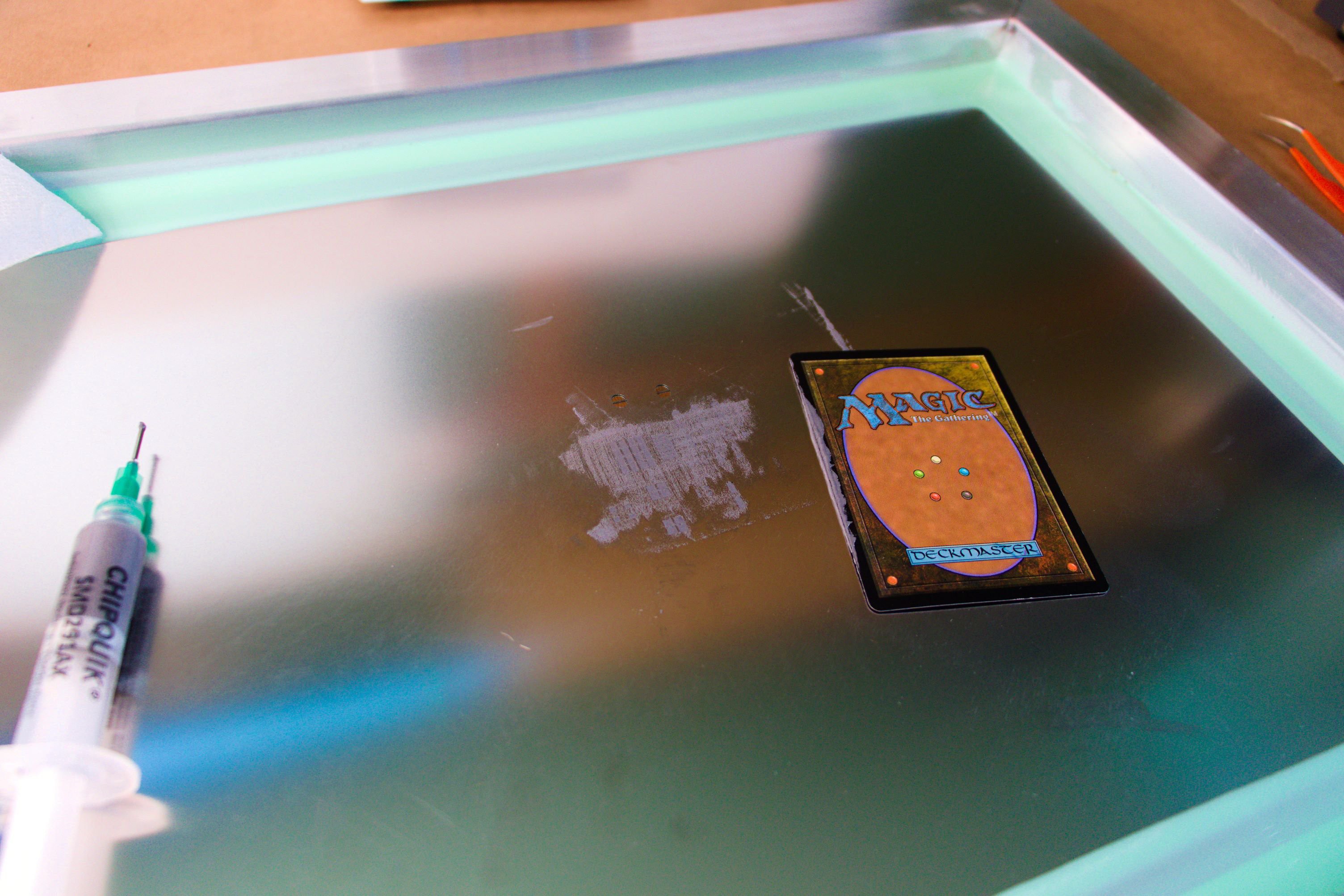
This was my first time using an actual solder stencil and hot-plate reflow rather than daubing on solder paste and using the hot air station. Turns out, using an actual stencil is way easier. Who'd have thought. Also turns out a scrap MTG card is a great paste spreader -- thanks to my gf for the improvised tool 🌈✨
Soldered up beautifully.
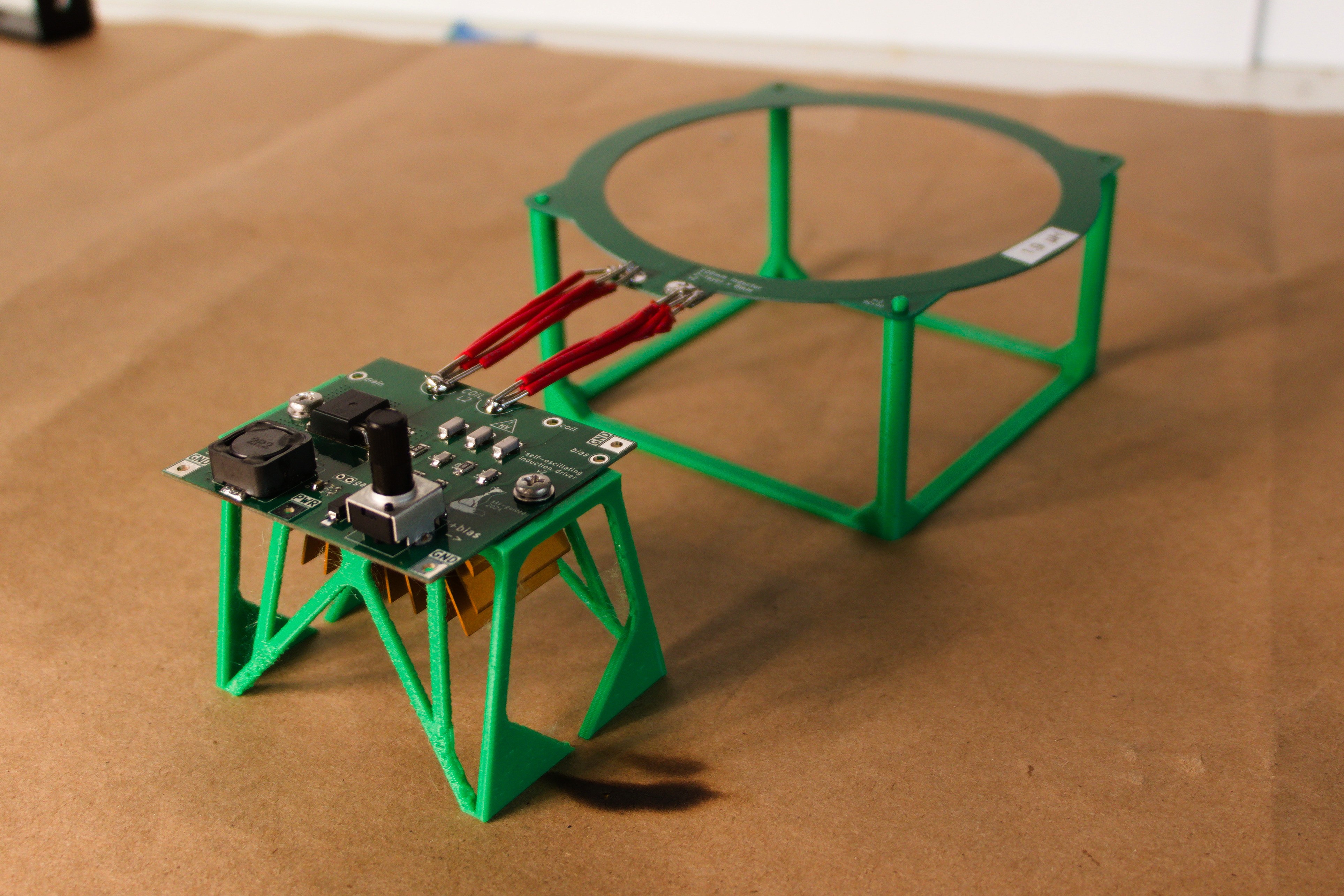
Since previous test coils had their 18ga wires badly overheat, I used bundles of 4x18ga to connect the board and test inductor. This is either a hacky kludge to get more surface cooling area, or a way of making bootleg litz wire -- take your pick.
Heatsinking for the mosfet is on the bottom side of the board -- you can see some of the orange fins peeking out. (There was an odd misadventure of the board flexing and making poor contact with the heatsink until I was able to melt down the kinda-thick phase-change thermal interface pad with the hot air station.)
I designed the board to use a duo of 0.1µF and 10µF capacitors for input power smoothing/decoupling... then realized during assembly that in my capacitor kit, those values aren't rated to enough voltage. 6.8nF was the highest value that fit in the 0603 footprint with a 50V rating. Fortunately the power input looked stable enough under load.
I spent quite a while futzing with the circuit and adjusting components trying to track down what looked like self-oscillation. Turns out nah I was just being a silly goose; the potentiometer was upside-down relative to v0.1 and I'd been turning it the wrong way, in spite of having triple-checked during board layout and marking the orientation on the board.
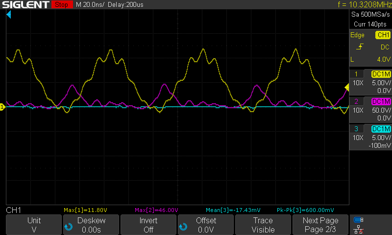
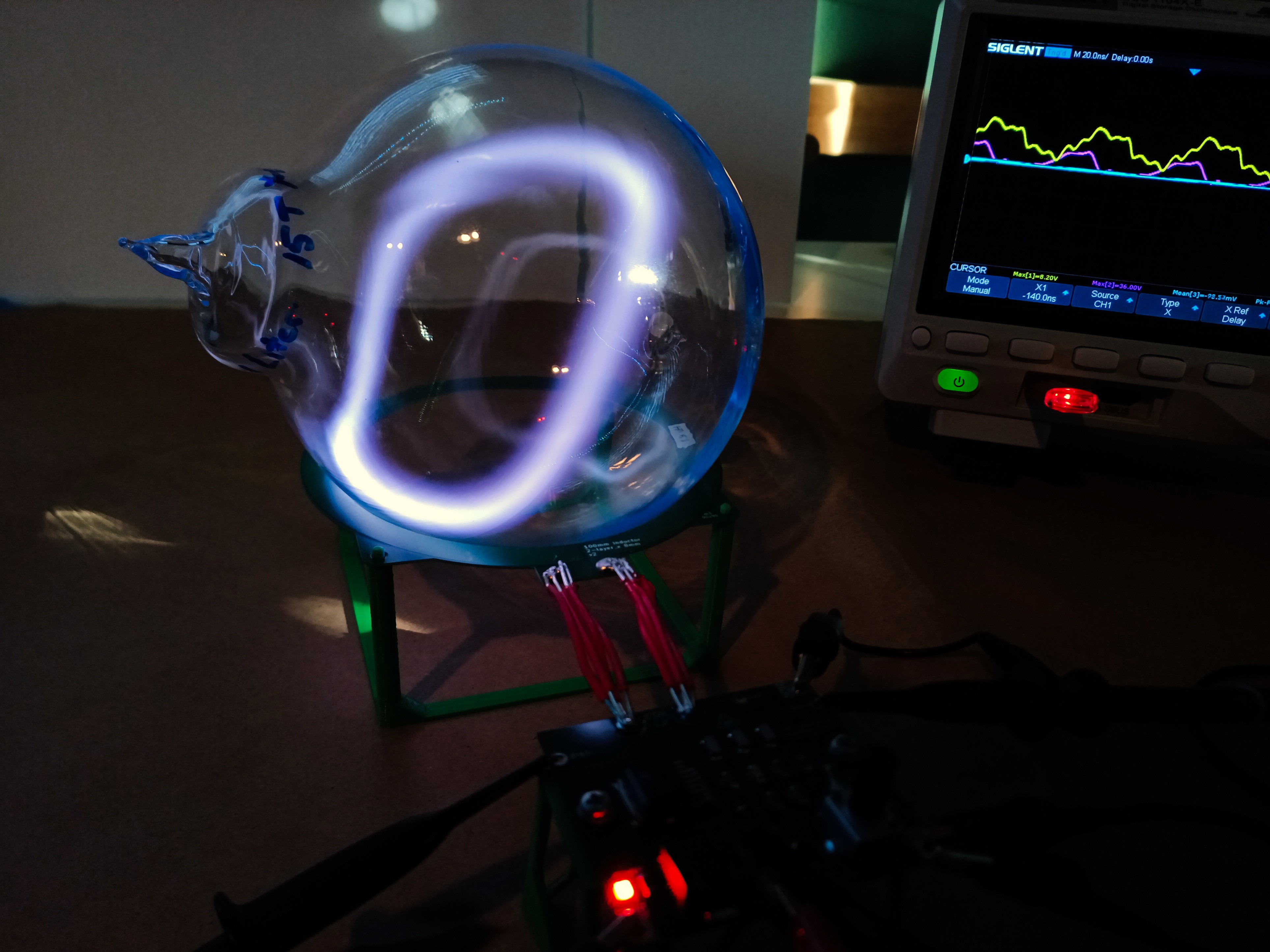
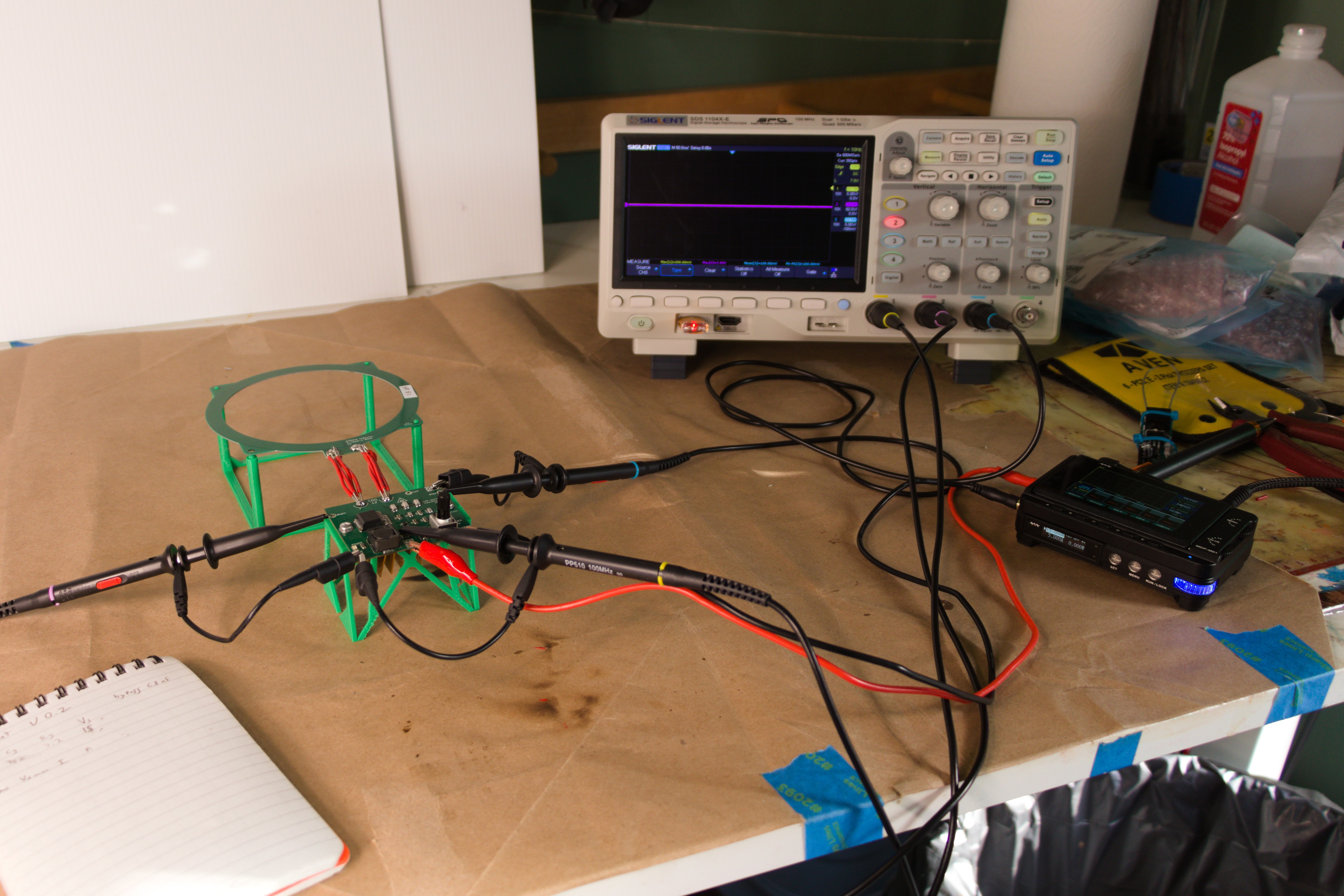
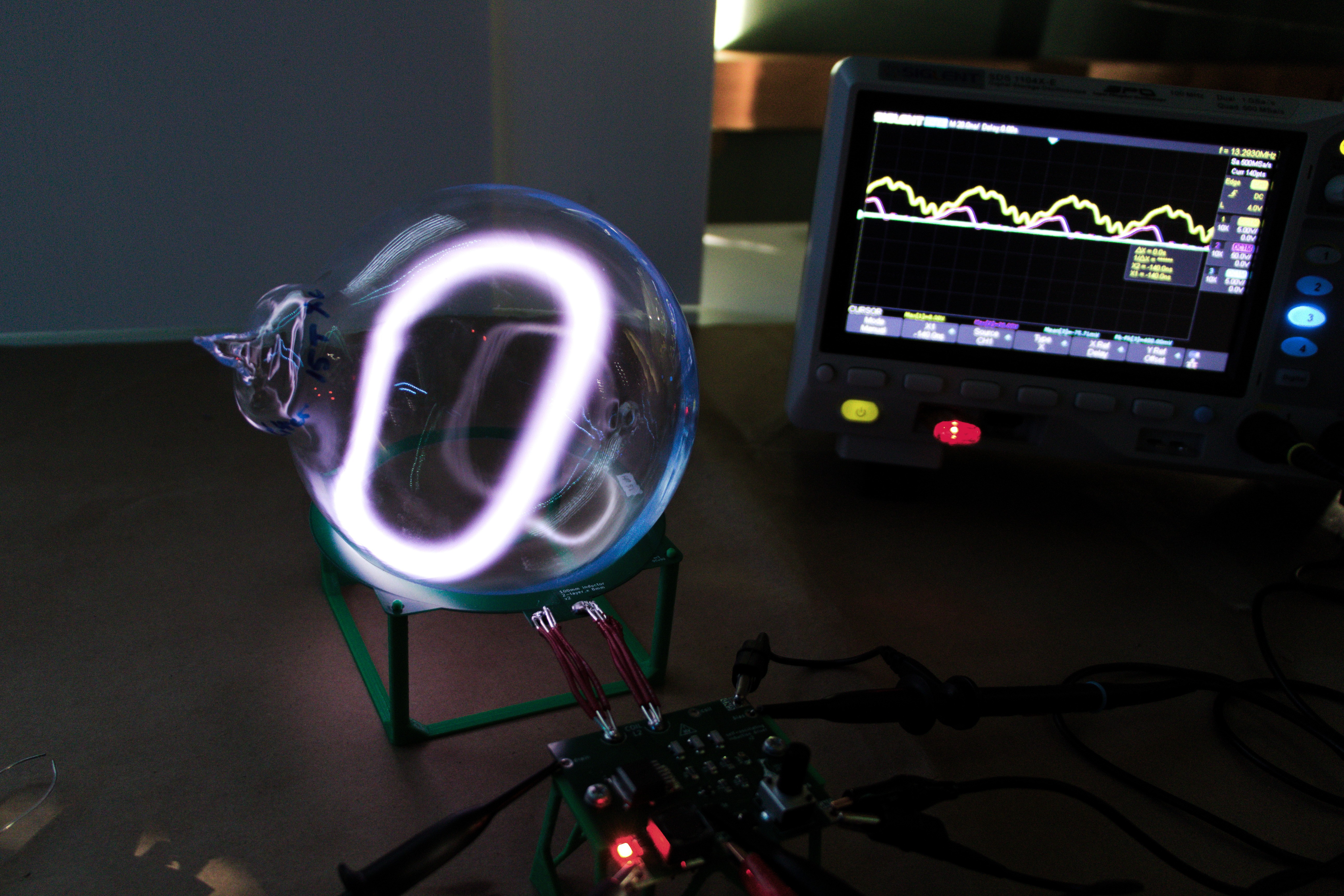
Clearly still needs some tuning but this is the basic waveform I expected. Yellow trace is gate (5V/div), purple is Drain (50V/div). Interestingly I was able to get strong oscillations and a running toroid even at 12V supply, when BackMacSci talked about 18V being the minimum for his setup. I'm hoping that adjusting Rg will reduce some of that higher-frequency ringing. [EDIT: Turns out this was mostly poor probe technique!]
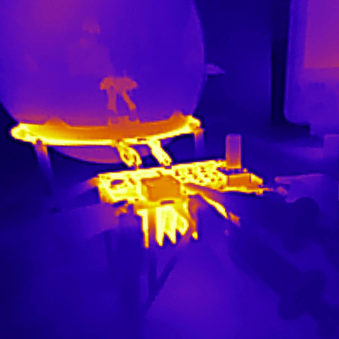
The PCB inductor still gets immediately and disconcertingly hot, even with much more dissipation area that the initial wire coil.
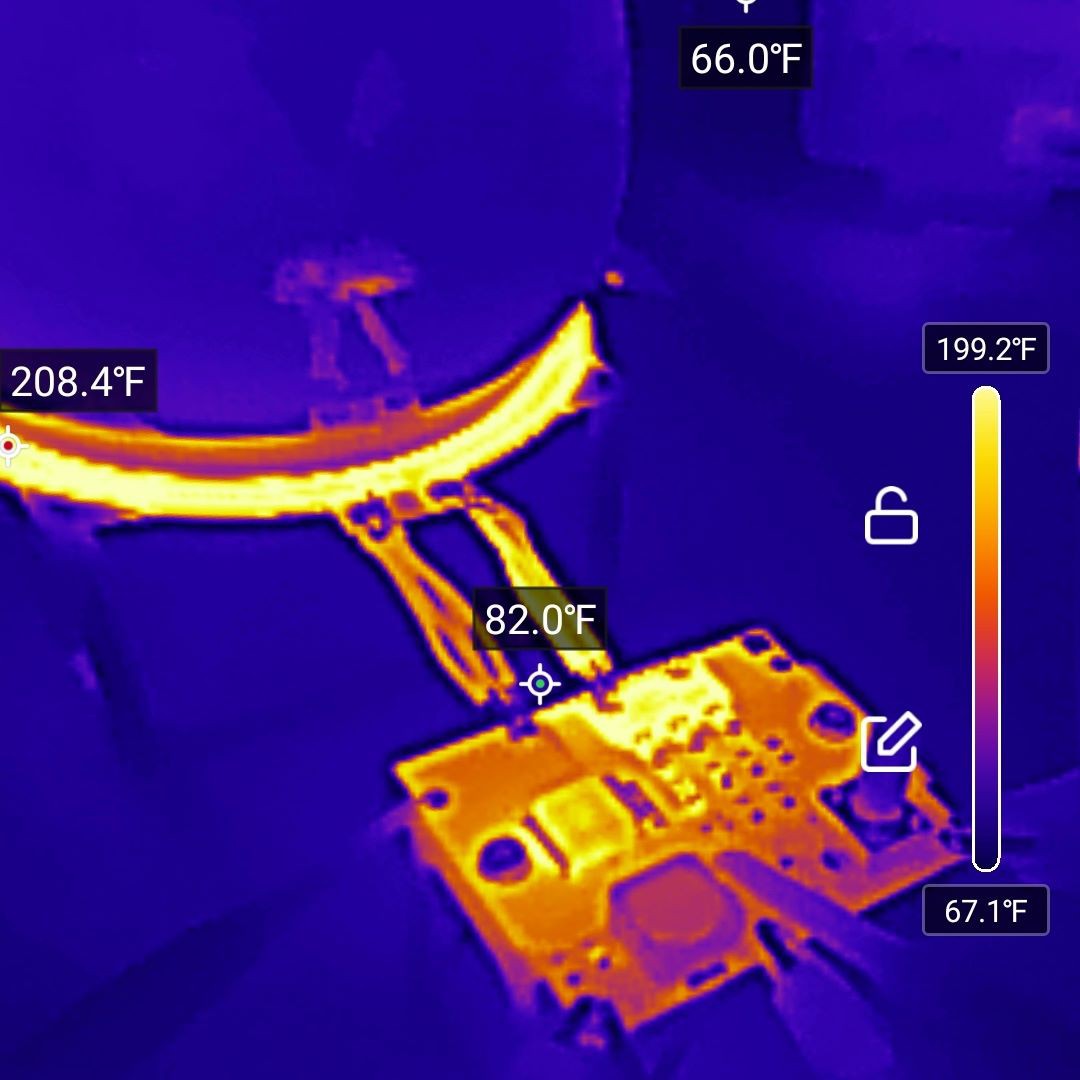 There's also distinctive heat buildup around the primary capacitors. Downsizing to a bank of three (from five) might have been asking a bit much.
Good news is that the underside heatsink is indeed sinking heat. The mosfet gets hot quickly too, but I'm hoping better circuit tuning will help.
Here's another photo of the toroid:
You can see that the o-scope waveform is all wonky when the toroid is actually toroid-ing.
For these tests, I was using a Miniware MDP-XP power supply. I'm a big fan of that tool -- it's tiny, usability is great. It also runs off of USB-PD, and in tracking down a variety of odd behaviors I ascertained that the USB power brick I was using may have been rated to 20V and 5A... but not both of those at the same time. Full load was causing substantial voltage sag.
Next tests: a beefier bench PSU. Stay tuned!
Discussions
Become a Hackaday.io Member
Create an account to leave a comment. Already have an account? Log In.