 sky-guided
After a year away, I'm returning to this project. It's time to come back and fix the deficiencies of Version 1.
The Problem
Version 1 of the plasma toroid controlled drive intensity with a potentiometer that adjusted oscillator mosfet bias voltage, which in turn changed the switching duty cycle. This isn't a great method of control. Changing the duty cycle introduces a variable phase delay which is harder to tune for. Also, since the drive is a sine wave running a low duty cycle leaves the mosfet in an intermediate half-switched state for longer, which isn't great for efficiency. Finally, low duty cycles would often result in loss of oscillation if the plasma was extinguished for any reason.
The better method is a dynamic high-side current limit.
I'm accomplishing this with a buck converter based on TI's "Simple Switcher" line of ICs, specifically LMR14030SDDAR. This chip is a monolithic buck converter with integrated mosfet, and it really is simple to implement. It's also capable of running at up to 97% duty cycle which is perfect for a low minimum dropout. Here's the reference circuit from their datasheet:
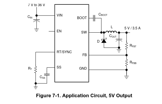
This is a perfectly normal buck converter topology. Most buck converters are designed to hold a fixed output voltage -- in this case, the ratio of resistors Rfbt and Rfbb create a voltage divider. Voltage at the pin FB is compared to an internal 0.75V reference, and the switching duty cycle is adjusted accordingly.
But we don't want a fixed output voltage. Instead, we want to measure the device current, and if the drawn current is too high we want to reduce the output voltage until current falls to the desired limit.
The Solution
Here's my circuit:
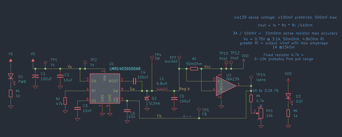
INA139 (ic U2) is a current-sense amplifier. It measures the voltage drop across the shunt resistor R3 and outputs a small voltage, with gain set by the combined value of R5 and RV1. This voltage is fed back to the feedback pin of the buck controller IC. The small capacitor C6 adds some low-pass filtering to reduce oscillation, plus some noise rejection.
If the measured current is low, a correspondingly low voltage is produced by U2 and the gain-set resistors. As a result the buck controller thinks it needs to raise the output voltage and increases the duty cycle (up to the 97% maximum). If the measured current is high and U2 outputs a higher voltage than the FB pin internal ref of 0.75v, the buck controller reduces the duty cycle until equilibrium is reached. RV1 being a potentiometer makes this current limit adjustable.
I'm leaving in my messy notes about trying to work out component values to make this transfer function do what it's supposed to. Seems like a good illustration of the design process -- these circuits don't come fully-formed from pure inspiration. These component values will probably still change!
On The Bench
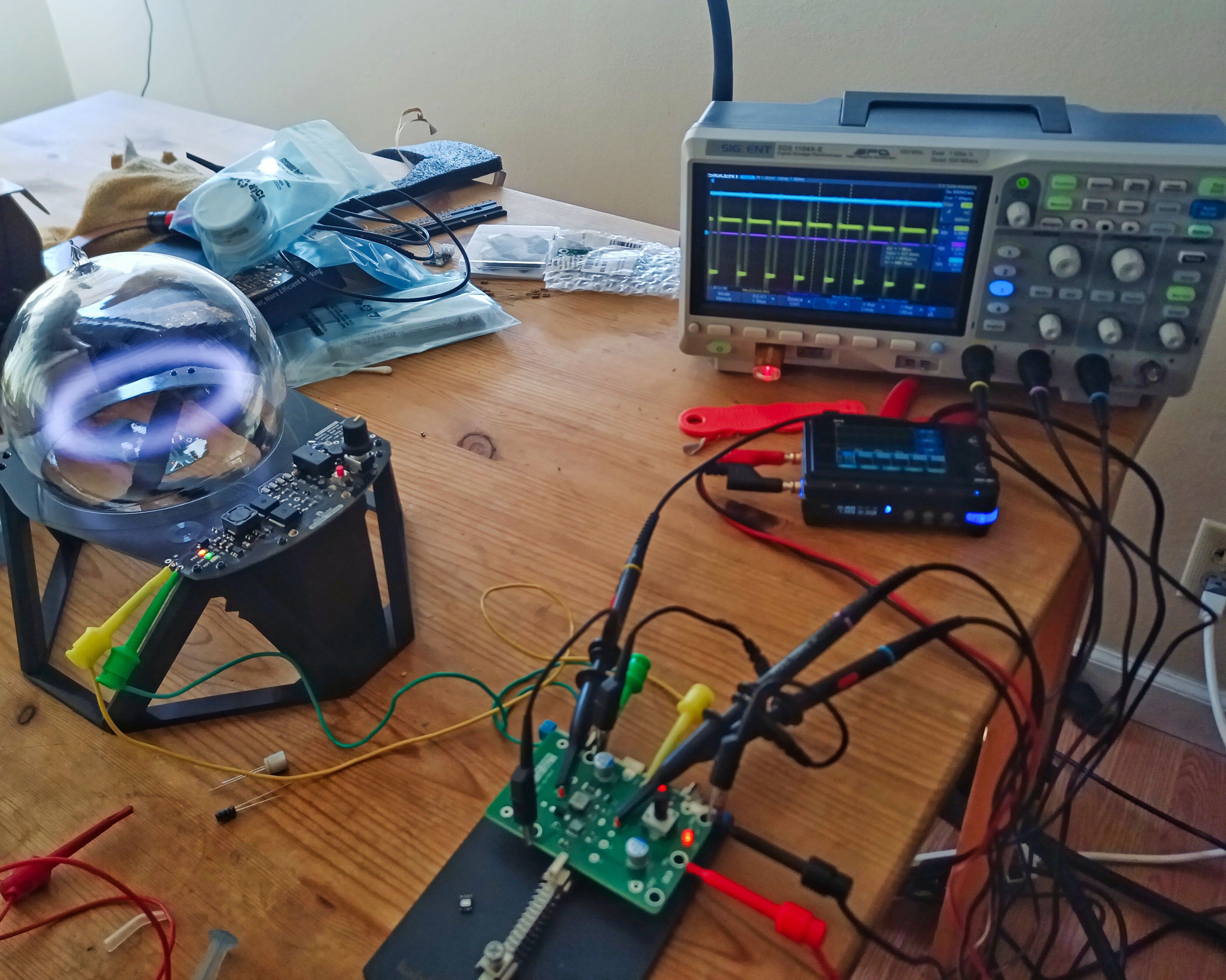
Although I had some initial befuddlement due to soldering the controller IC on backwards, the circuit worked perfectly. I'm able to fully and smoothly control the allowable current all the way from USB-PD supply max down to below the minimum needed to sustain the toroid. This control method is much more stable and robust than shifting the mosfet bias voltage. Hooray!
I didn't start testing this module directly with a plasma toroid driver board. Initial basic functionality was verified using a li'l 12V peltier module as a load -- it's the closest thing I had on-hand to something purely resistive.
Here's the scope view:
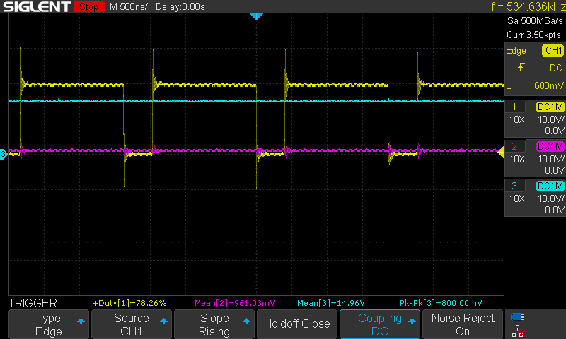
Yellow is the buck switch, purple is the feedback voltage, blue is the output voltage (input is 20v). Switching frequency is about 500kHz. Everything is nice and well-behaved.
Next up: a better arc start.
Discussions
Become a Hackaday.io Member
Create an account to leave a comment. Already have an account? Log In.