 sky-guided
The pushbutton arc start in version 1 was cool, but also kinda trash. First, it was super inconsistent with starting ionization on a cold xenon globe, and often took several seconds of button-pressing to do so. Secondly, the subcircuit had a bill of materials that was way too expensive and was over-reliant on specialty components. The photoflash IC in particular both cost >6USD each (at quantity ten) and is an out-of-production last-time-buy part. The arc start module also needed two different specialty transformers and a particular model of gas discharge tube. Ridiculous.
Design for Production
What the arc start module actually needs to do is produce several kilovolts. A pulse of DC is fine, a few milliseconds of HV AC is fine, whatever.
It took me a weirdly convoluted series of steps, but the end solution is easy: a donkey-simple flyback converter using one of the same xenon trigger transformers as the last design.
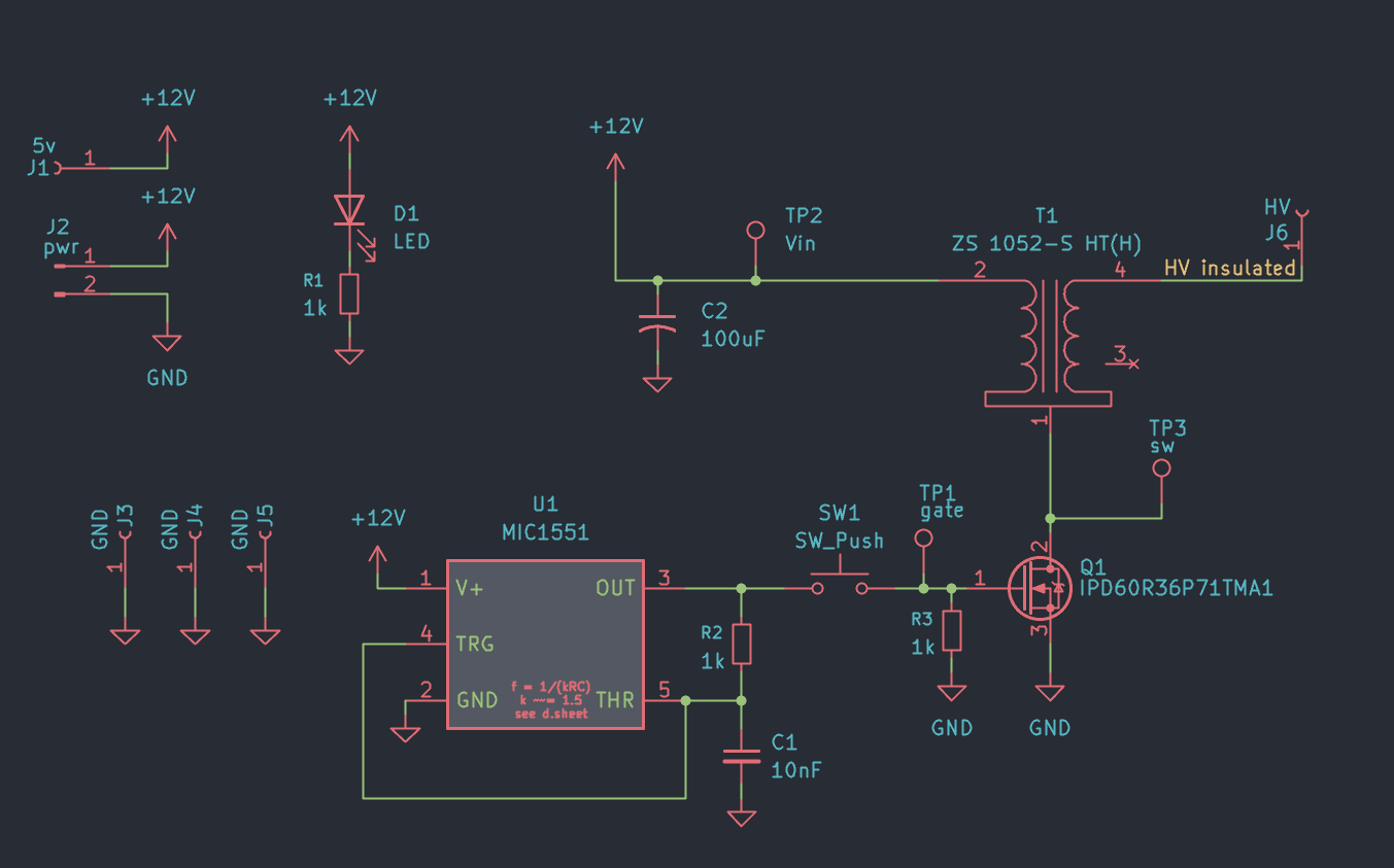
MIC1551 (U1) is a spinoff from the classic 555 timer but reconfigured to generate a 50% duty square wave with only two external components. The values shown here run at ~43kHz which was chosen as an arbitrary ultrasonic frequency. This hasn't been optimized at all, and doesn't really need to be.
T1 is running as an autotransformer which is a bit unusual for flyback converters, but that's how the component is pinned so it's what we've gotta run with. I've done quite a bit of searching for other candidate transformers, but there's very few which are designed to withstand such a high output voltage in a compact package.
Here's the scope, zoomed in to one pulse:
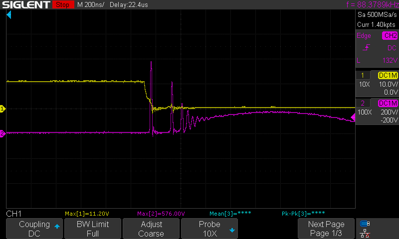
Yellow is mosfet gate, purple is mosfet drain. With a transformer turns ratio of 1:10 that's theoretically 5kV+ of output, which roughly corresponds to the maximum arc length I can draw.
Toroid ignition is 100% reliable with this design. It works every single time, and it works no matter where on the globe I touch the HV output.
Running 1A @12V can create a hot and sizzling continuous arc. If there's nowhere to arc to, the output instead produces distinct corona discharge and a strong smell of ozone. For the plasma toroid striker I'll be limiting the entire module to something like 300mA input, which is plenty to create a couple milliseconds worth of HV from the energy stored in the 100uF capacitor.
The board is very generously spaced for such a simple circuit.
Ok, but what's up with the footprint at the north edge clearly designed for a totally different transformer? Well...
A goofy path to get here
During development of plasma toroid v1 I tested using a generic "arc lighter kit" to start ionization. See example listing photo:
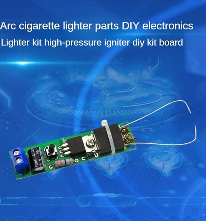
It didn't work well at all, so I abandoned the line of inquiry. Only later did I realize I missed something very obvious: I needed to tie one of the transformer secondaries to the toroid driver's ground. Having done that, it became a fully reliable ignition method.
Obviously I didn't want to just ziptie this piece of tat on to my PCB, so instead I set to re-implement their circuit. Here's a handy reference schematic from Quartz Components
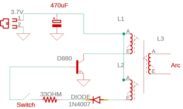
The transformer is an inscrutable black potted cuboid with primary, feedback, and output windings. The primary and secondary irregularly emerge from the potted block as thin wires coated with an enamel that's basically impossible to solder through. BJT D880 uses the feedback winding to self-oscillate. Based on measuring output inductance I estimate a primary:output turns ratio of something like 1:65. These transformers are available all over aliexpress for very cheap, but it took me ages to track down the actual part number as XR000425 from shenzen yuandongan electronics.
The specific D880 BJT isn't available from US vendors. For my test implementation I chose a BJT that seemed probably close-enough.
My trial board did oscillate and produce a mediumish high voltage, but way less than what I needed. Changing values of the feedback resistor didn't help much.
Asking myself "what problem am I actually trying to solve here?" lead to grabbing breadboard, a same-footprint mosfet, and a 555 to drive with a fixed duty cycle.
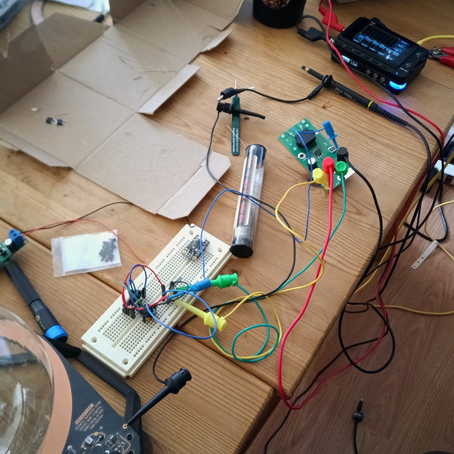
which worked quite a bit better, starting the toroid reliably.
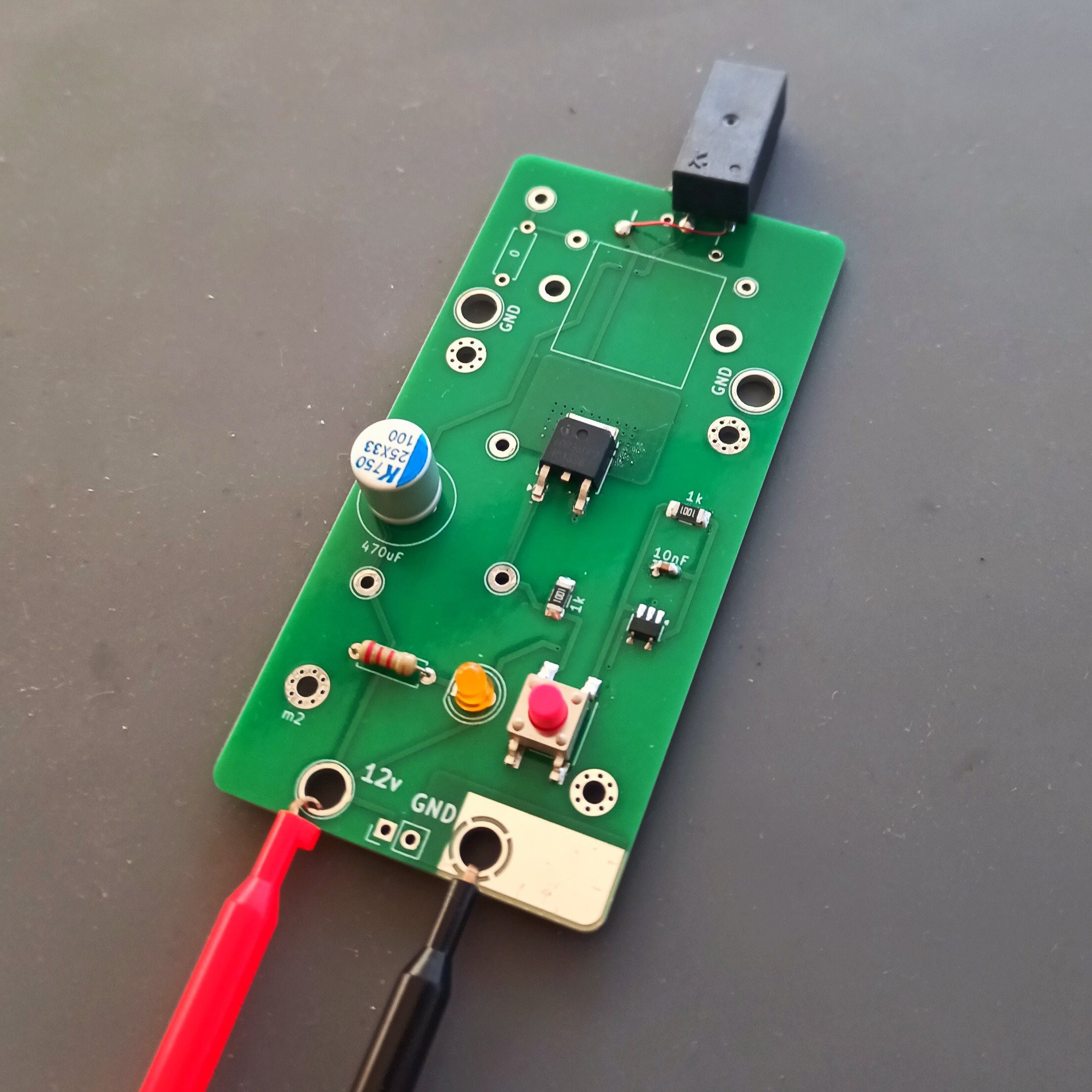
So I spun a new PCB, now using the MIC1551 timer. This version was very zappy. The grey not-square thingy is a printer cover / hold-down bracket to secure the transformer block to the board using screws (instead of a ziptie or glue).
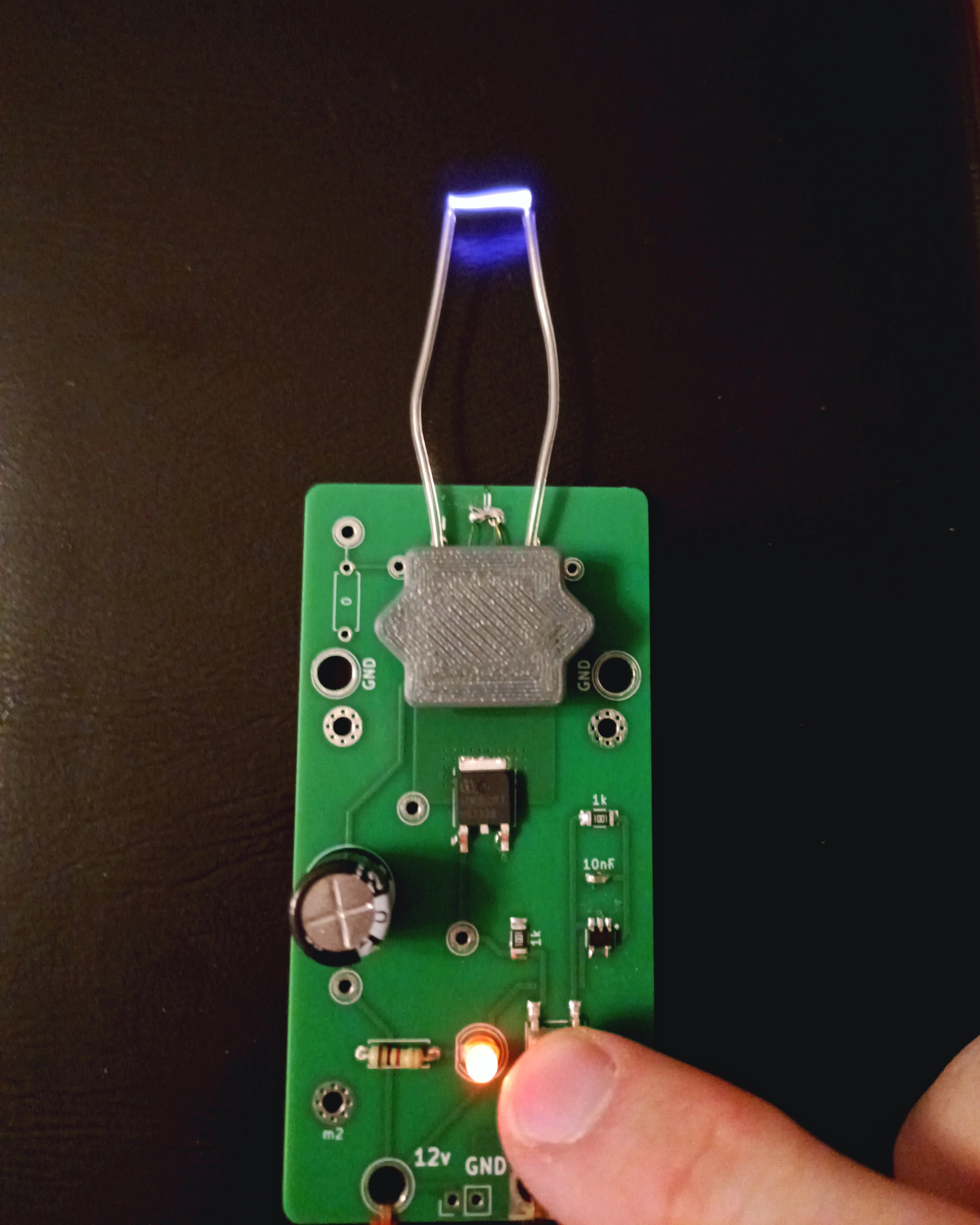
So zappy that if the outputs where too far away to arc, the transformer would instead breakdown either internally or through the insulation+air where the wires emerged, causing immediate destruction.
I could obviously ramp down the power or run at a lower duty cycle or something, but to be honest a design based on the "arc lighter" potted block transformer didn't actually fulfil the goals of "design for manufacturability". Its angel-hair leads were incredibly annoying to solder and I really don't want to say "search aliexpress for a part which looks kinda like this" in an assembly BoM.
Another round of searching for suitable transformers lead me right back to the specialty xenon trigger transformer I'd been using originally. Funny thing is I'd completely misremembered the ZS 1052-S (and friends) as being in the "not recommended for new designs" lifecycle, but nope, it's an active part which is reasonably priced. Good news is I already had some on-hand to test with.
That's how I ended up with the bodge-job shown earlier in this post.
Thanks for reading. Next up: further refinements of the toroid oscillator core.
Discussions
Become a Hackaday.io Member
Create an account to leave a comment. Already have an account? Log In.