 sky-guided
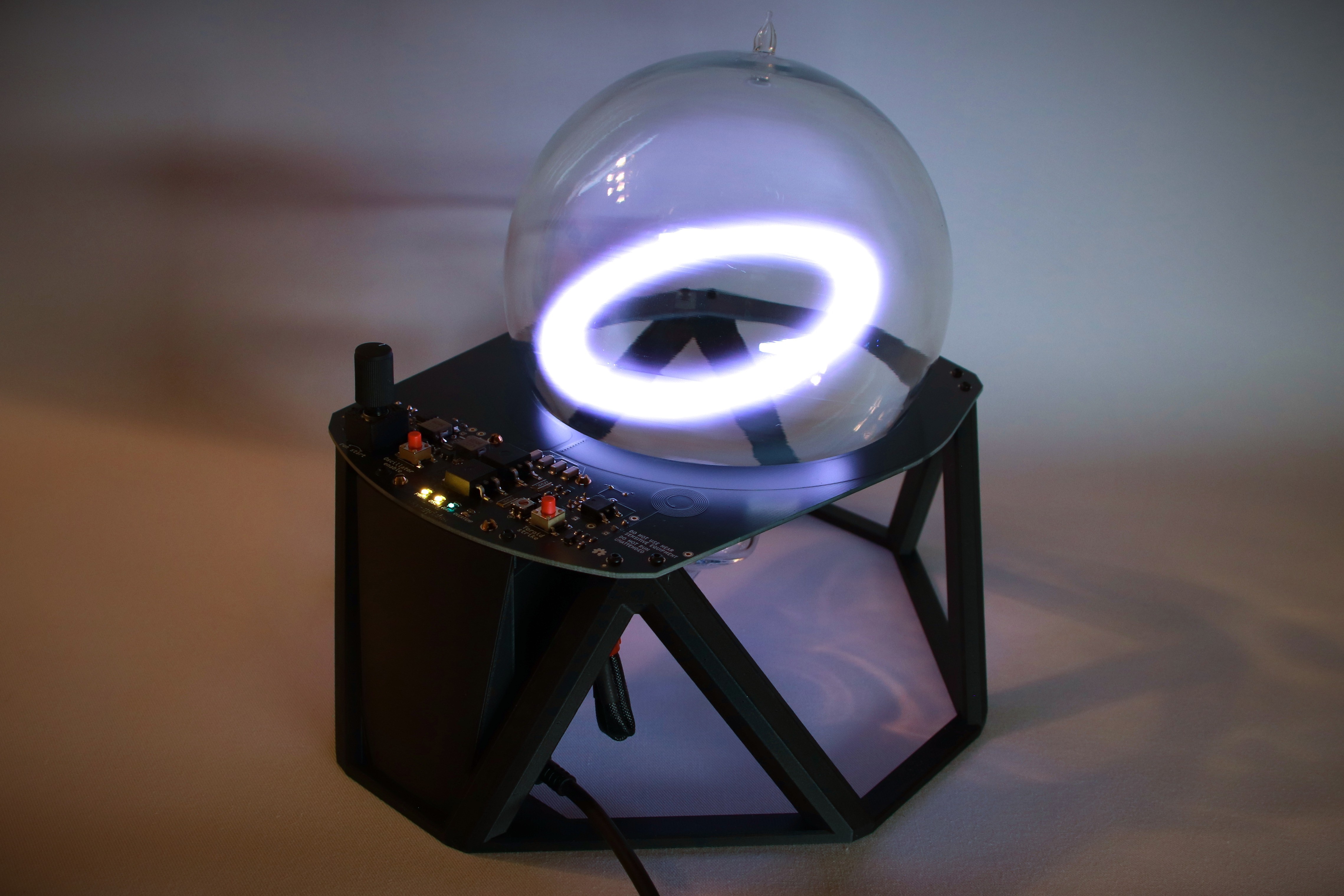
Plasma Toroid Version 2 is complete. You can even buy an assembled board!
Here's the full schematic. You'll probably need to open in a new tab and zoom in.
![]() What's Changed from V1?
What's Changed from V1?
 What's Changed from V1?
The new canonical home for this project's design files is a Codeberg Repository.
Here's an overview of improvements in Version 2:
Adjustable Current Limit
The new on-board buck adjustable current limiter is discussed in-depth in Project Log #12.
Since that log was written, I've changed the switch regular to a slightly-higher-power 5A module for folks who want to try running at higher voltage/amperage than USB 65W. I've also added solder jumpers to switch the knob to a "higher gear" adjustment range, or bypass the regulator altogether.
Soft-switch Enable Toggler
It's nice to shutdown the oscillator while the device is still connected to power. Using a soft-switch toggle rather than a physical switch also should (in principle) make the oscillator always start off when power is first connected. In practice the capacitor does seem to retain enough charge that there's some "stickiness" to the previous state.
This implementation was inspired by a helpful StackExchange post. Thanks, Endolith.
Prototyping was done on a standalone breadboard.
Input Power
I've re-added a TVS / reverse polarity protection diode (D5) at the power input. There's also now 100uF alupoly capacitors used throughout the board, where previously I'd tried to exclusively used ceramic SMT caps. These through-hole alupoly capacitors are soldered to the underside so a sleek topside appearance is preserved. More bulk capacitance at the power input makes oscillator and arc starts much more consistent and stable.
Simplified Arc Start
Version 2 uses a simpler high-voltage flyback. Full details are in project log #13.
One thing I've discovered is the polarity of the HV output really does matter. One polarity of primary winding works magnificently at ionizing the xenon, but the other struggles. I think the proper configuration is first-pulse-negative but it's been a bit confusing to 100% match the schematic and pinout of the HV transformer, so do your own tests.
The final transformer selection ZH1052-1(H) is oriented for high galvanic isolation, and even has a wire lead suitable for a striker!
Aesthetic Changes
The new version is planned for black soldermask PCBs, rather than the fancy transparent soldermask stackup of version 1. If you fab it in transparent soldermask I'm sure it'll still look great, but I didn't go nuts optimizing the precise trace routings as an aesthetic concern.
Indicators are now using neutral-white and sky blue LEDs, plus red for overheat alarm. The overall vibe is more "alien technology". I know blue LEDs are frequently abused but trust, me it looks great.
The BoM has been updated for a sleeker control knob, and I've designed a printable potentiometer cover for even cleaner aesthetics.
Monolithic support print
Version 1's support structure was designed as collection of flat-printed parts, assembled together with heat-press inserts and machine screws. This was a compromise design meant to avoid quality limitations of the Ender 3 I'd been using, along with a vague notion of flat-pack shipping.
The updated design is a single monolithic 3d print. I've upgraded to a much more modern printer and no longer suffer from degraded quality/reliability on tall, spindly parts. A unified monolithic print skips an entire assembly step and permits a curved face for the heatsink shroud. The PCB attaches to the support structure with thread-forming screws so heat-press inserts are no longer needed.
Refining the Oscillator Core
The oscillator core is almost unchanged!
Upgrading to adjustable current control meant I could convert the gate bias control knob to a set-and-forget trimmer potentiometer.
MOSFET gate resistors have been upgraded to much more robust 1020 "wide" components rated for two watts. I'd spent ages chasing overheating with the dual 2125 resistors in v1, thinking it was some kind of flaw. However when at last I actually calculated expected gate current from gate charge and switch frequency it was obvious that the gate restors really need to be >1W devices. The irony is the gate resistor was explicitly called out as "2W" in BacMacSci's original schematic but I apparently hadn't taken the rating seriously.
Mosfet selection: unchanged.
I did a whole series of tests investigating different driver MOSFETS. My interest was focused on Infineon's IPB320N20N (D2PAK) and IPD320N20N (DPAK, smaller) based on a tip sent in via email, claiming they could run cooler. Their spec sheets were compelling and it seemed extremely plausible.
I pursued the smaller DPAK fets for a while but they couldn't quite dissipate enough heat. Perhaps if I'd run three in parallel it'd work, but that was getting a bit goofy. IPB320N very nearly took home the crown, but there was an odd little issue. With my existing IPB17N25 mosfets, setting a bias voltage just higher than the threshold for starting oscillation resulted in a near-perfect duty cycle for maximum drive power. This allowed all throttling to be done by the current limiter. However with the IPD320N, getting maximum drive power required first increasing the bias voltage to oscillation start threshold, then reducing bias a bit for best duty cycle. This was unsuitable for a set-and-forget bias voltage.
I did many more searches for good parts, but no other candidates came close unless I made a switch to GaN or SiC. That was a change I wasn't going to pursue since suitable parts were much more expensive and switching characteristics are different enough to likely need multiple rounds of prototyping.
So in the end, my mosfet selection was correct the first time around. Nice!
Design for Manufacturability
I've decided to offer this board as a very small-run kit with the PCB pre-assembled. Multiple people fabricated their own builds of Version 1, and collectively it's much more efficient to do one batch of PCB fab and assembly rather than having every individual person procuring their own. This is intended to still be a project for electronics enthusiasts rather than mass-market consumption.
DFM in Version 2 is considerably better than Version 1 but still not perfect. A plurality of the components are either not substitutable or have less-than-commonplace specs. The MIC1557 oscillator in particular seemed like a good idea at the time, but for manufacturability I'd be better off with a traditional 555 and a few more support passives. It's a high candidate for replacement if I decide to do minor board revisions.
I've spent many rounds chasing down parts availability on JLCPCB, alongside "patch" release version updates for the substituted part numbers. I'll also still need to do a little bit of hand-assembly even for the production boards. Overall BoM cost is comparable to version 1, but version 2 is far more feature-rich.
What's Next
Watch this space -- there's one more project update coming very, very soon.
Discussions
Become a Hackaday.io Member
Create an account to leave a comment. Already have an account? Log In.