 Ted Yapo
So I wired up some 74AC logic to drive the horizontal board, and hooked up an AD9200 ADC to the vertical board. I found that the maximum usable sampling rate was just under 30 MS/s, with good results at 28. The limitation seems to be the speed of the LEDs and the matrix PCB itself.
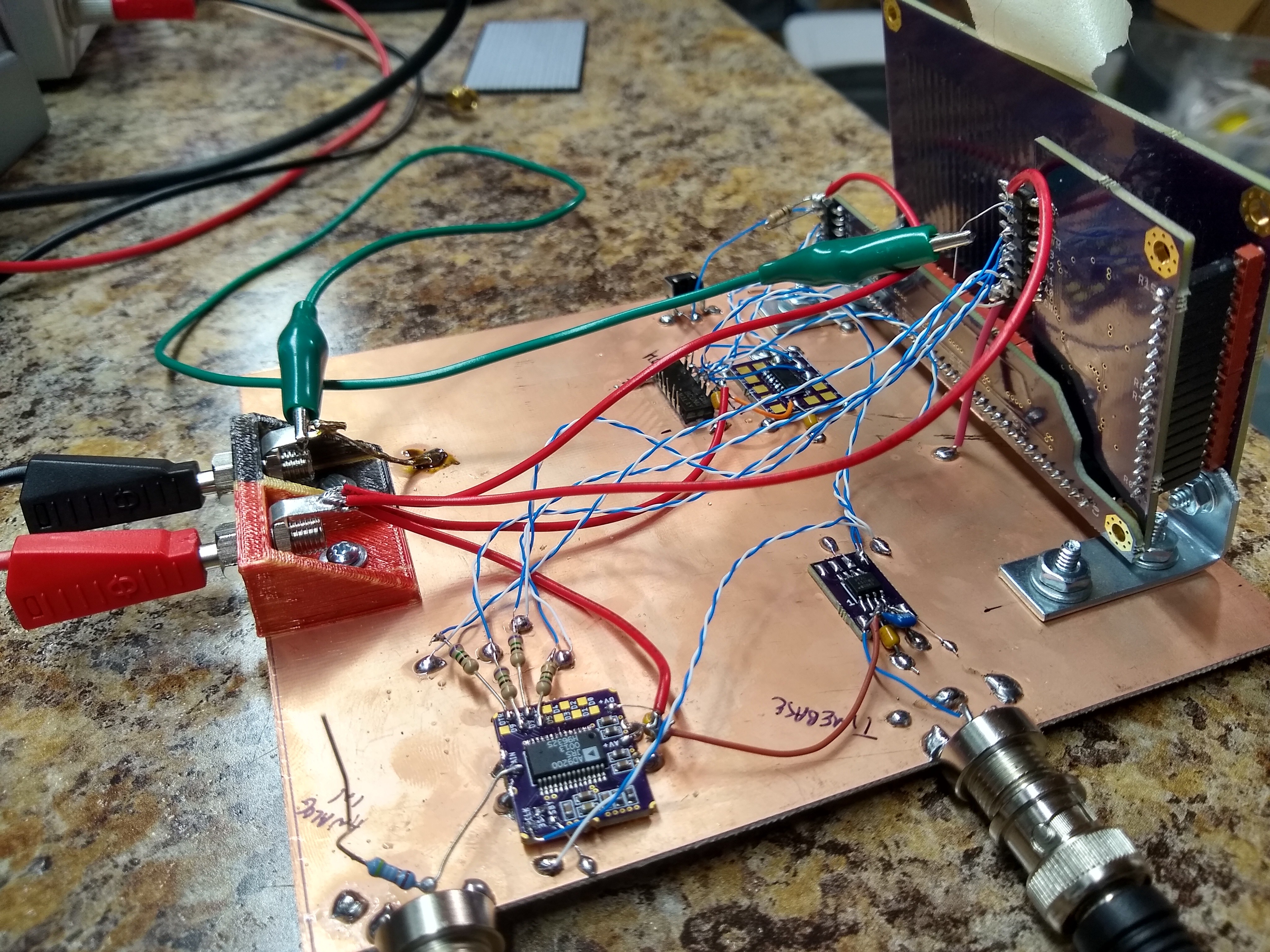
The AD9200 is in the lower left, with the top four bits (it's a 10-bit ADC) driving some 100-ohm twisted pair lines through source termination resistors (those wires were long enough to warrant it). The input jack on the lower right is for the timebase signal - my DDS only goes to 25 MHz, so I added a x4 PLL on the prototype to see how far I could push things - that's the PLL in the SOIC-8 package. At the top left, I have a 74AC74 and 74AC00 to cycle a single zero through the horizontal driver shift registers.
The AD9200 datasheet specifies a maximum rate of 20MS/s, but I found it produced good results for the upper 4 bits (all I care about) out past 30 MS/s.
I simulated the thing in logisim before building it just to be safe. It turns out that logisim has an LED matrix component, so I could actually simulate it pretty well:
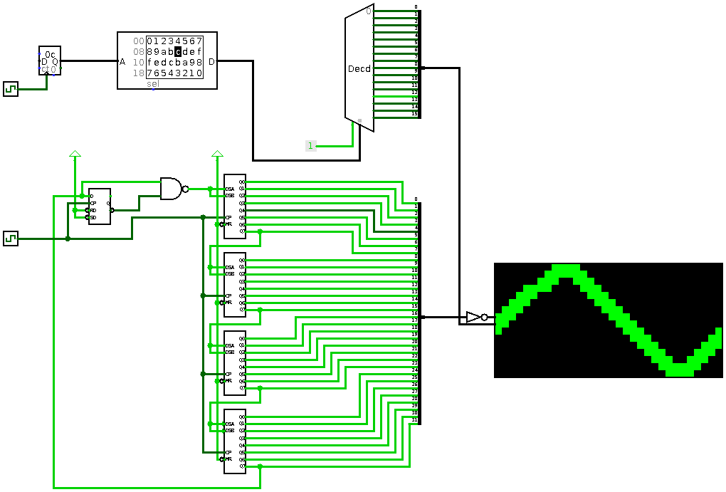
The bottom part is the horizontal driver - four 74AC164 shift registers that reside on the horizontal driver PCB. The flip-flop and NAND gate are dead-bugged on the copper clad. I made 512 mistakes when I populated the LEDS - they're all backwards, so I had to mess around with the drivers a bit. For instance, the horizontal shift register requires a single low output to ripple through the register, which complicates the logic. When I assemble an LED matrix correctly, this will be much easier.
This also would have been easier with an FPGA, but then there's the 3/5V problem. I have a bunch of GAL16V8's around, but I just couldn't go *that* old-school...
The top part of the simulation stands in for the ADC - it's just a counter, RAM, and decoder with a stored triangle waveform.
It works on the hardware, too. Here's a 1.69 MHz sine wave sampled at 28 MS/s.
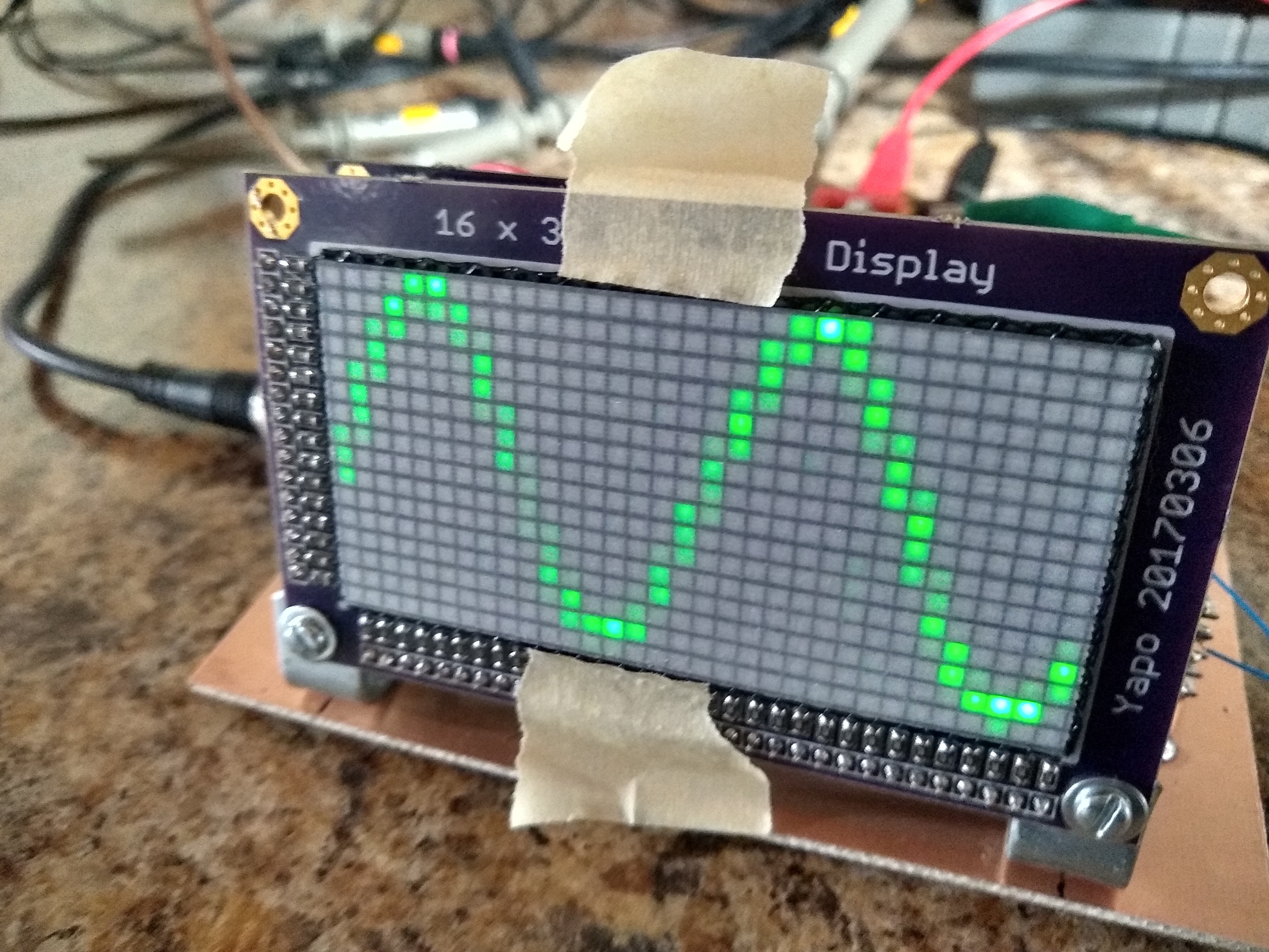
At this sampling rate, the display is pretty dim. In fact, it only has full brightness below around 2 MS/s. At higher sampling rates, the display becomes progressively dimmer. It's not really surprising - at 28MS/s, those LEDs are blinking at 28MHz! Between the PCB layout and the capacitance of the LEDs themselves, there's a limit to how fast they can blink. I wanted to see how far you could push the original concept, and this is probably it! You might get it to go a little faster with a better PCB layout or maybe better choice of LEDs, but this is probably pretty close.
I avoided the whole issue of triggering the sweep by 1) making the sweep free-running, and 2) driving both the horizontal timebase and the analog input from two channels on the same DDS generator, so they are always in phase. This makes things a lot easier to test. To make a usable oscilloscope, you'd need to add some triggering mechanism. I have plenty of ideas here, and have simulated some promising solutions, but we'll have to see how well they work on the bench.
I didn't even try to measure it, but I'm sure this thing is an emissions nightmare. I tried all sorts of sampling frequencies between 1 and 30 MHz tonight, and frankly I'm a bit surprised there is not a mob of angry ham radio operators knocking at my door with torches and pitchforks.
I have to admit, I'm a bit disappointed that the LEDs are the limiting factor. I'll have to think about it a little more.
I can't resist one more image that I think really shows how this project is different from a traditional digital scope.
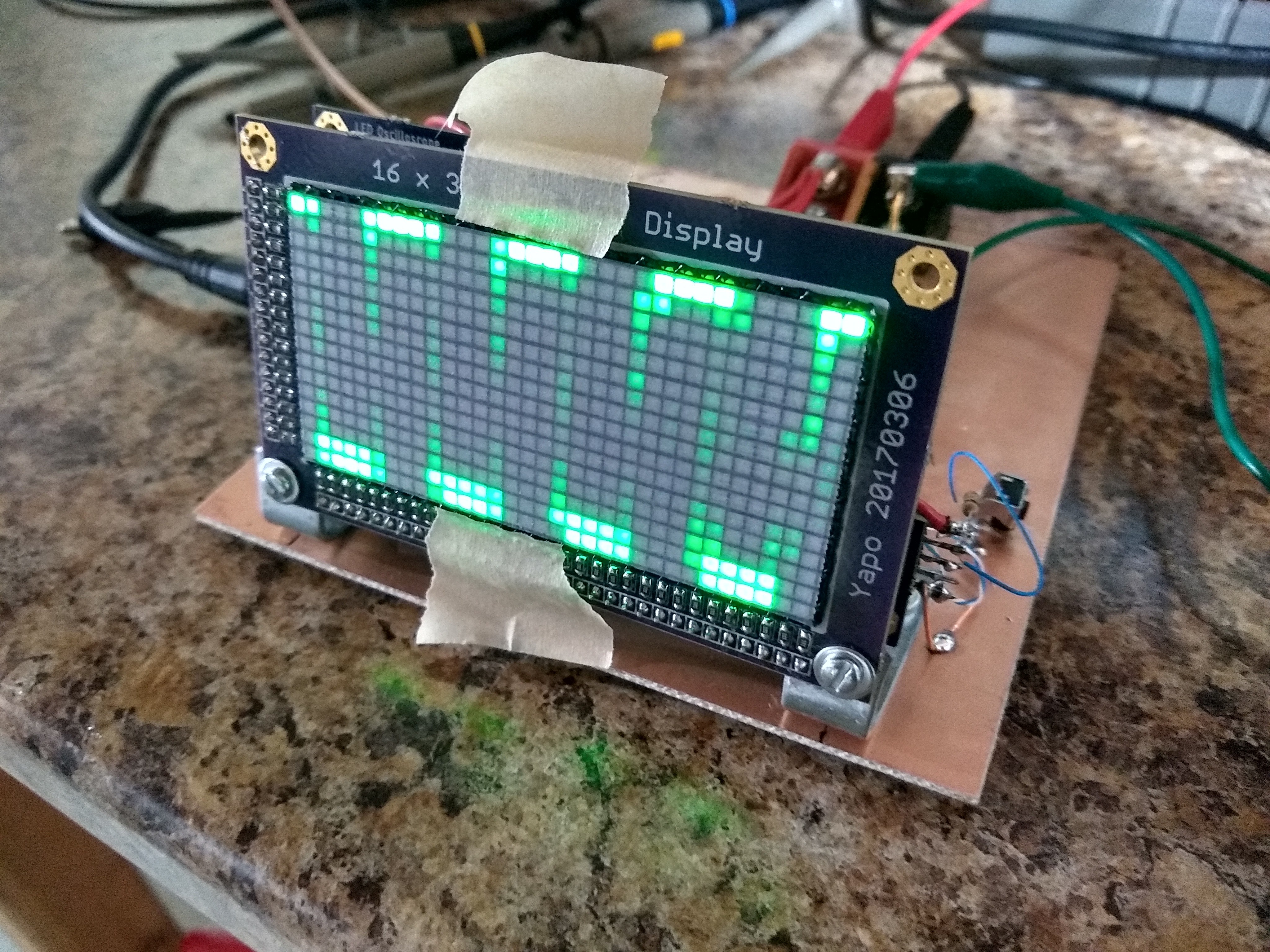
It's got none of that dead every-pixel-the-same look of a digital scope. Instead, it has more of the softer feel of a CRT.
Discussions
Become a Hackaday.io Member
Create an account to leave a comment. Already have an account? Log In.
The Multiplex display have quite a bit of capacitance from multiple LED. So the display driver would have slow tr/tf. e.g. 250pF load for GAL16V8 is ~10ns which is a large portion of the 35ns period.
Are you sure? yes | no
Yes, this is the problem. I wonder how much you could improve the situation using a 4-layer PCB and trying to build the rows and columns into lumped approximations of transmission lines - in other words, absorb the LED's Cj into the transmission line structure. It might be worth some experiments with a single string of LEDs to see how fast they can be driven with the right PCB design.
Are you sure? yes | no
Thinking in term of impedance, it is going to be low - low trace inductance with LED (capacitance) distributed along the trace. You would need a low impedance driver.
The transmission line would be a distributed model like this:
https://en.wikipedia.org/wiki/Distributed_element_model#/media/File:Line_model_Heaviside.svg
If you think in term of faster tr/tf for charging/discharging a large capacitance load quickly, you would also need a beefy driver.
May be something like 74ABT: Output drive capability IOH / IOL = -32 mA / +64 mA :) Or it could be just your regular 74xx24x drivers wired in parallel.
I hope you have buffered the ADC outputs too as the buffer would isolate the ADC from ground bounces and improve on the drive characteristics.
Are you sure? yes | no
@K.C. Lee I haven't been good about documenting the other PCBs (future log), but the vertical driver board has two 74AC138's (the LED matrix needs a 1-hot input decoded from the binary output of the ADC) and two 74AC540s to invert and drive the rows. The ADC doesn't drive the LEDs directly.
I initially designed it with a register as the driver (74AC574), but needed to invert the signal since I mounted the LEDs backwards. The register was there to avoid seeing decoding transients from the 74AC138 on the LEDs, but I haven't noticed any at the speeds I've been able to go.
I'll check out the 74ABT family. That +64mA is interesting. Even better than the 74LVC (+/-32mA) I had been considering.
Are you sure? yes | no
The ABT was probably the last beefy 5V drivers type before they gave up on first incidence wave switching and gave way to Reflected-wave switching used in PCI.
The tr/tf is much larger than the propagation delay, you should not worry about about transmission line effects i.e. reflections etc.
Are you sure? yes | no
Those waveforms fade in a delightfully analog-y way. As you imply in your post, I'd be curious to see how this does in a radiated emissions chamber..
Are you sure? yes | no