 Dimitar
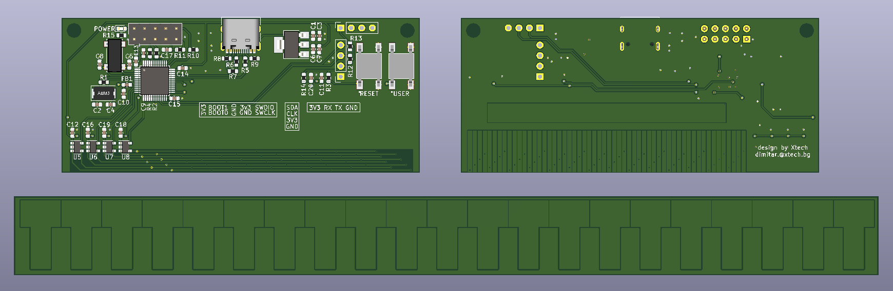
From the image above you can see the front, the back and the t-scale for my caliper. Bellow I will list a few things I considered while making this design.
- I chose the STM32F103 used in the blue pill because it is capable, cheap and schematic is available. People love it. Hopefully I could get help with the code if needed.
- I made the MCU board with 2 layer PCB, the t-scale is single layer board. I did not want to make the paths and vias small. Since I knew the proportions I decided to make everything larger than the one you will find in a store both caliper. All of this will make the board cheap to manufacture. A set is $2.25 with shipment from China.
- It is populate on one side and the components are fairly large. I decide not to get a stencil. The component count is small and the size of the them is relatively large. I think I will get away with manually applying the solder paste. I don't get paid for this projects, so cheap as possible is the name of the game.
- The through hole components are located on the top side of the board, so they don't interfere with the scale moving. Two holes are present for mounting.
- The 2x5 pin horizontal connector is for boot select, power and debugging.
- The 4 pin horizontal connector is an UART with power. If someone wants to implement a text based protocol for communication.
- The 4 pin vertical connector is made for a OLED 0.91" display (i2c). It should cover the central part of the PCB.
- USB 2.0 full speed with USB C connector for good measure.
- Two buttons, reset and a user button.
- Last but not least a power indicating LED. I always regret not putting a LED that indicates if my board is power or not.
Here are some links: schematics, BOM, footprints, gerbers.
Discussions
Become a Hackaday.io Member
Create an account to leave a comment. Already have an account? Log In.