 Dimitar
Hello all,
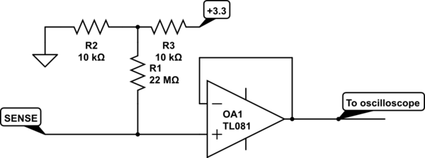
I have asked for help on the electronics stack exchange on what would be the best approach for the measurement of the resulting signal would be and also to solve the mystery of the negative voltage. I was given a task to make buffer so that a proper snapshot of the signal could be taken. This is the schema:
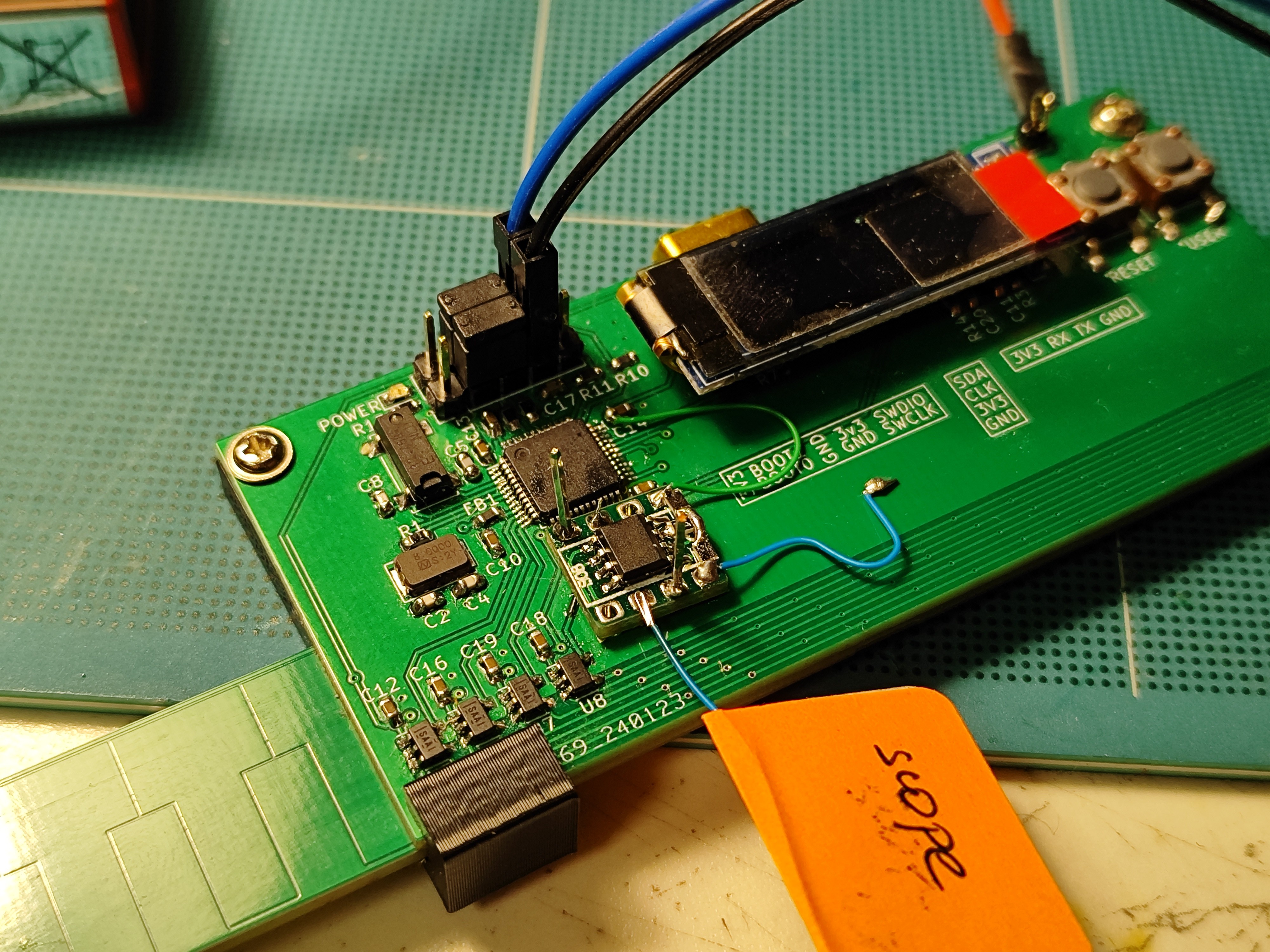
And this is how it looked on the board, some "mad" soldering skills there :D
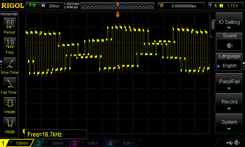
And the resulting signals is as follows:
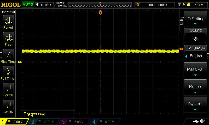
Offset of nearly 2V

We still have a little bit of 60Hz oscillation in there, but nothing too bad I guess.
And now we wait,
Cheers
Discussions
Become a Hackaday.io Member
Create an account to leave a comment. Already have an account? Log In.