Hello all,
First lets do a resume of what I have done so far.

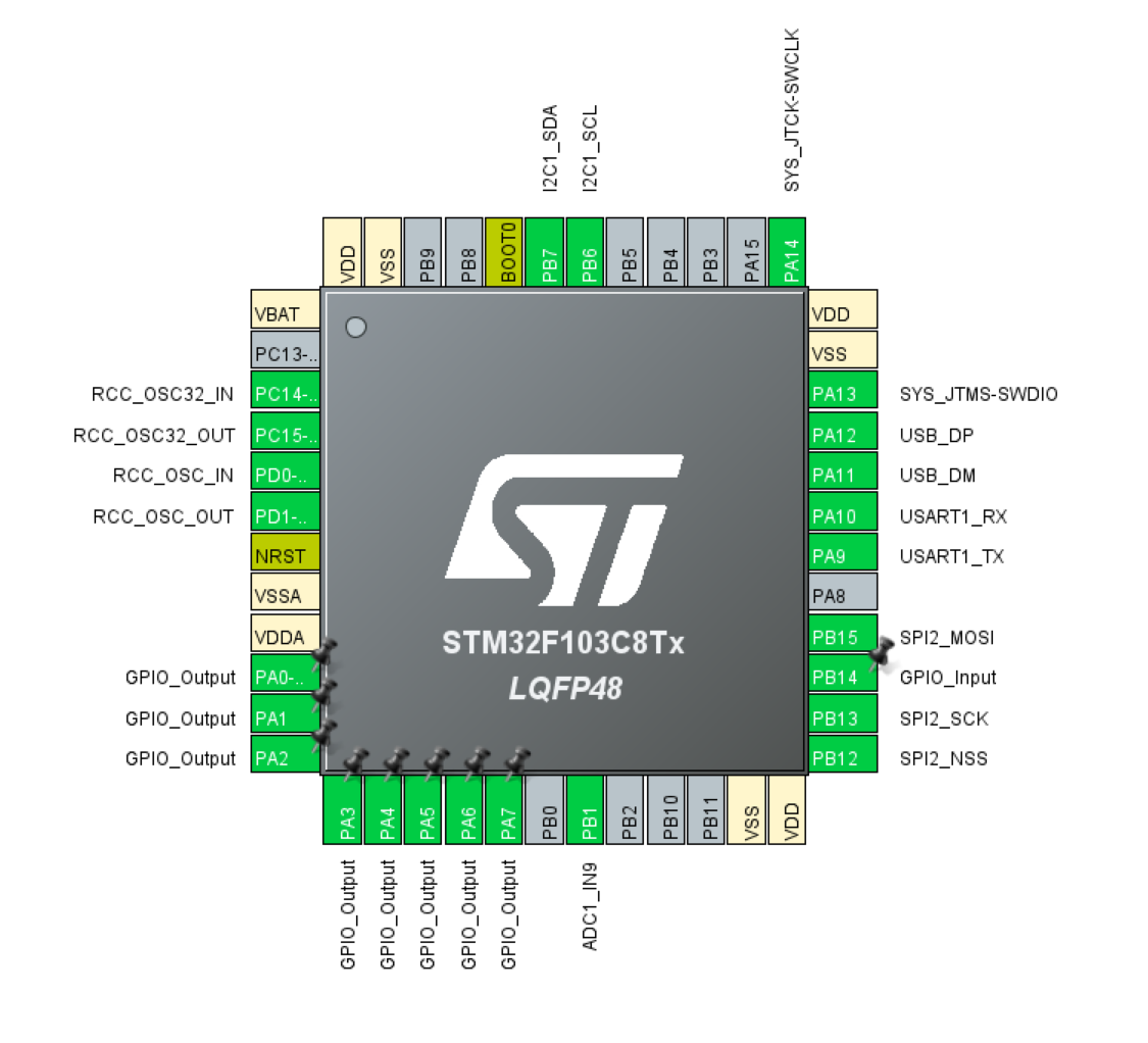
- All 8 pins of GPIO Port A (10-17) are connected to the excitation plates of the sensor. We are implementing bit banging to run excitation pins. TIM2 is set to interrupt every 15us. In the timer ISR the pins are changed according to the array with predefined values. The pattern repeats indefinitely. The pin state array is populated according to what we see from the caliper disassembled before.
- ADC1 channel 9 on pin 27 is used to measure the voltage of the pick up plate
- I2C1 is supposed to be used for the display, but I still managed to wire it the wrong way. See earlier log for more info.
- USB is working and we use as CDC. We can use it in collaboration with Serial Oscilloscope to see the output of the pick up plate.
- UART1 is wired to a header, but not used at the moment.
- SPI2 is connected to the Op Amp, gain can be adjusted.
- SWD for programming and debugging both with CubeMX and Arduino.
The challenges that stand before us
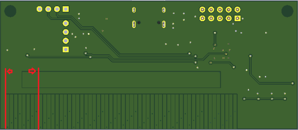
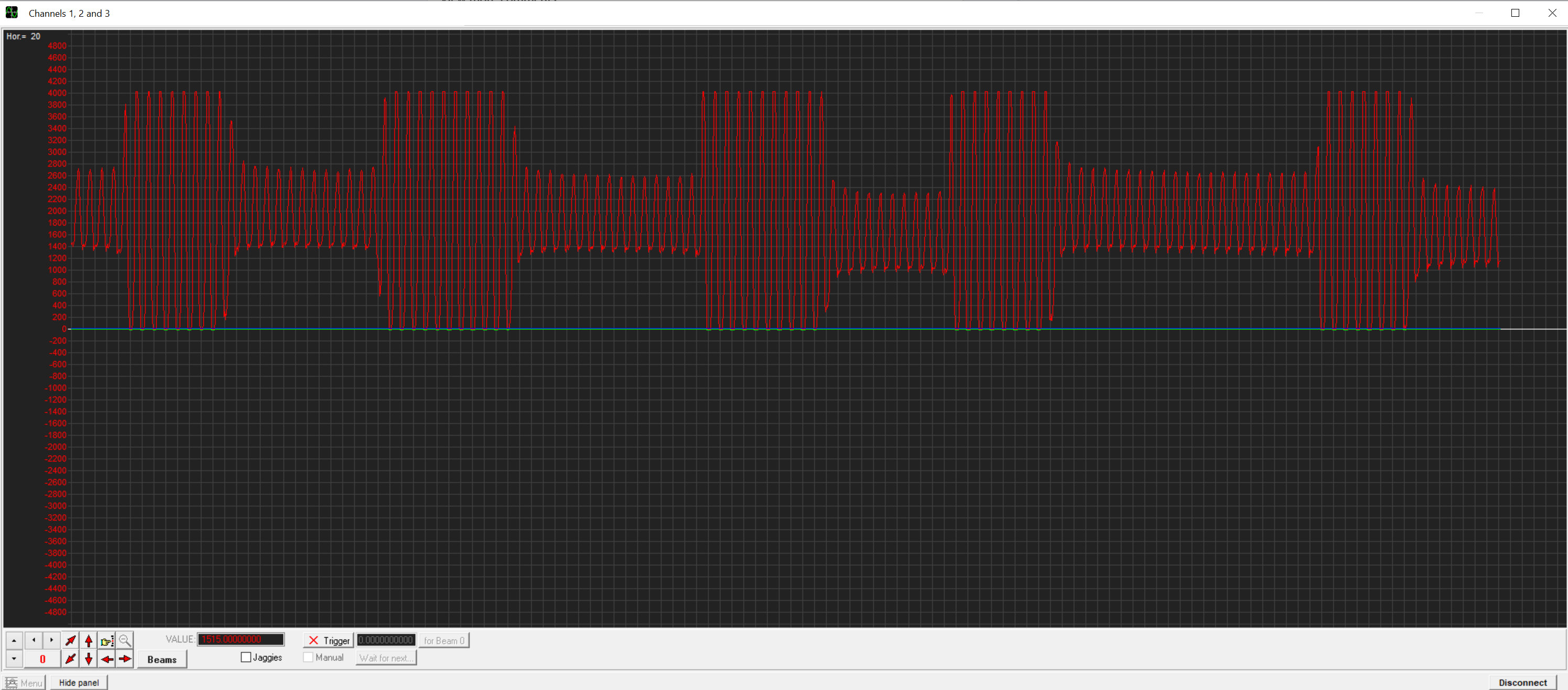
- I went through a bunch of patents. In all of them they say that this frequency of 15us is determined on the physicals size of the sensor. Unfortunately it does not gives a formula to determine the frequency. In my ignorance I made the sensor a bit larger thinking it might be easier to manufacture. If we compare the signal from the original caliper and our they are similar but not the same. Some experimentation might be need so that the output match.

- Since we added the op amp we have 50Hz noise on the analog input of the MCU. I would assume this is due to the noise of the AC power all around us. In the States people might pick up 60Hz. This could be fixed in two ways. One is to implement a Notch Filter in software and the other would be to do it in hardware. This means a new version of the PCB which I cant justify right now. We have not gotten all out of this one.
![]()
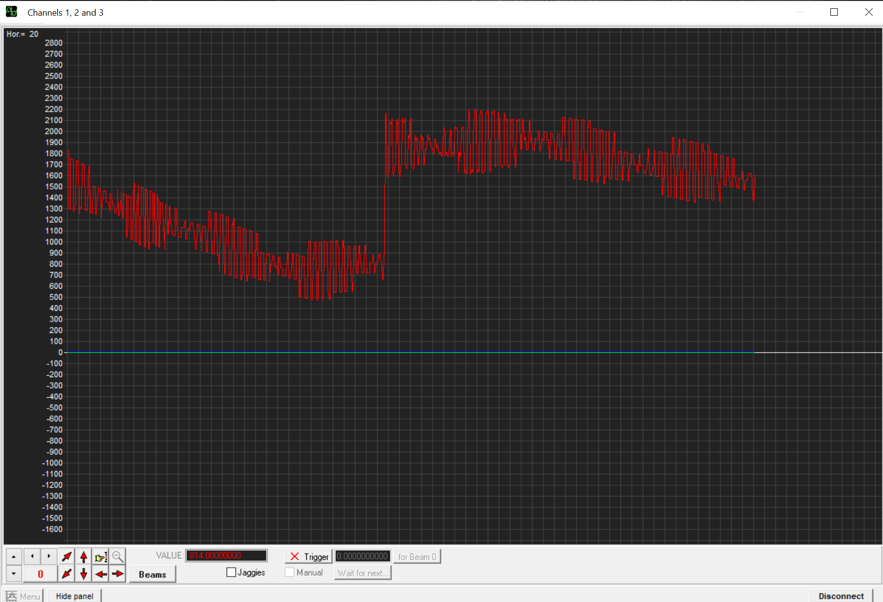
We are changing pin state every 15us. ADC conversion takes 2-3us and transmitting 5 chars total of 40bits over 115200 baud rate UART takes 347us without accounting for function calls and such. This means that we could not use Serial Oscilloscope to "see" in real time. Rather we could take a snapshot using DMA and then transmit the values over UART. This is picture of the 50Hz noise using the Serial Oscilloscope. You can clearly see when I am touching the board.
![]()

Since a few people have asked me I have uploaded the working version of the software both CubeMX and Arduino. Note that we do not have a algorithm for working out the distances yet as I was working out the signal conditioning schema.
Cheers,
M
 Dimitar

Discussions
Become a Hackaday.io Member
Create an account to leave a comment. Already have an account? Log In.