 Quinn
QuinnAs noted, I cut this out by hand.
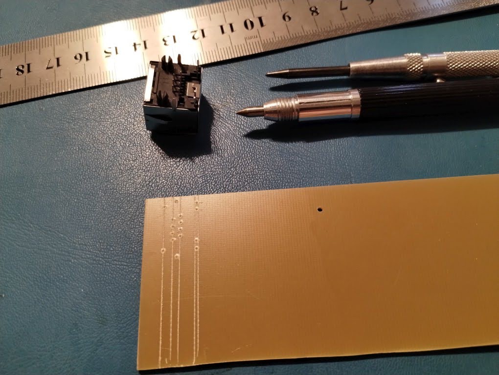
Component holes
I started by using ruler and scribe to add lines for the hole placements on the RJ45. These connectors don't fit into common strip board, which is part of the reason for making my own board. A metal created a nice pilot to drill.
I repeated this for the DC Jack, switch and placement for second RJ45
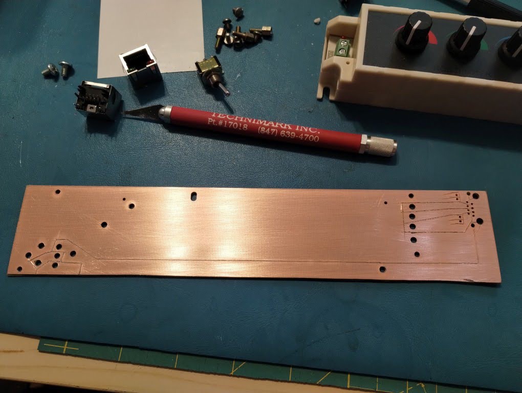
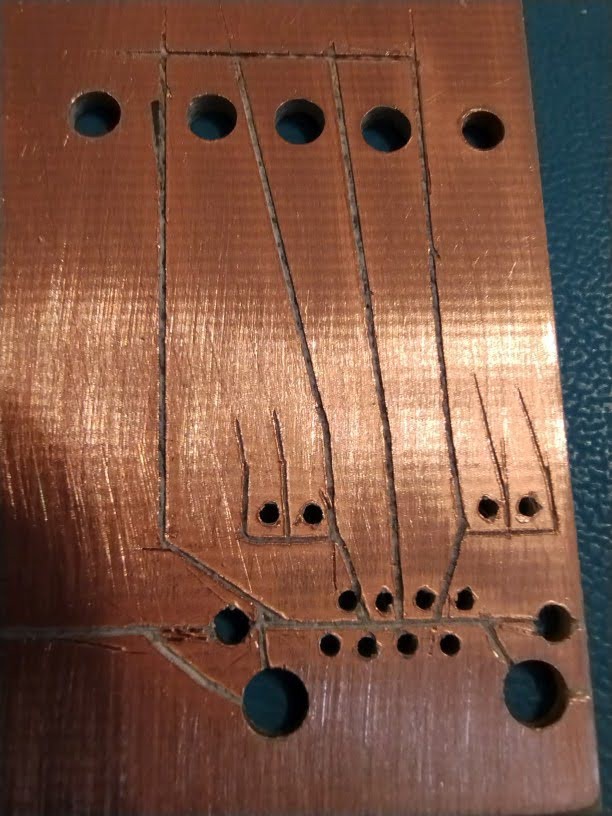
Traces
Next I drew out the circuit on the backside and use an exato and ruler to isolate the traces..
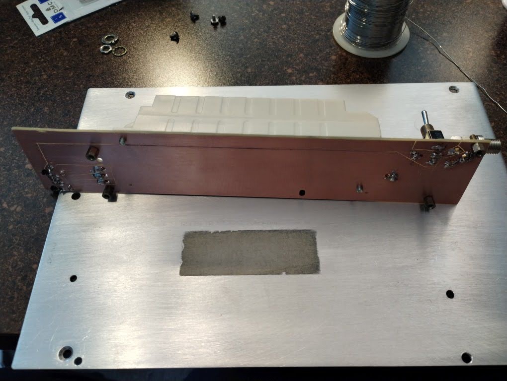
Mounting
Mounting holes were drilled and tapped. I took care to make sure the stand off holes did not connect to any traces but ground. While grounding the plate isn't required, the stand offs did handily end up doing so.
I also drilled a couple holes for wires to solder to for connection to the dimmer.
Result
I kinda love how manual and h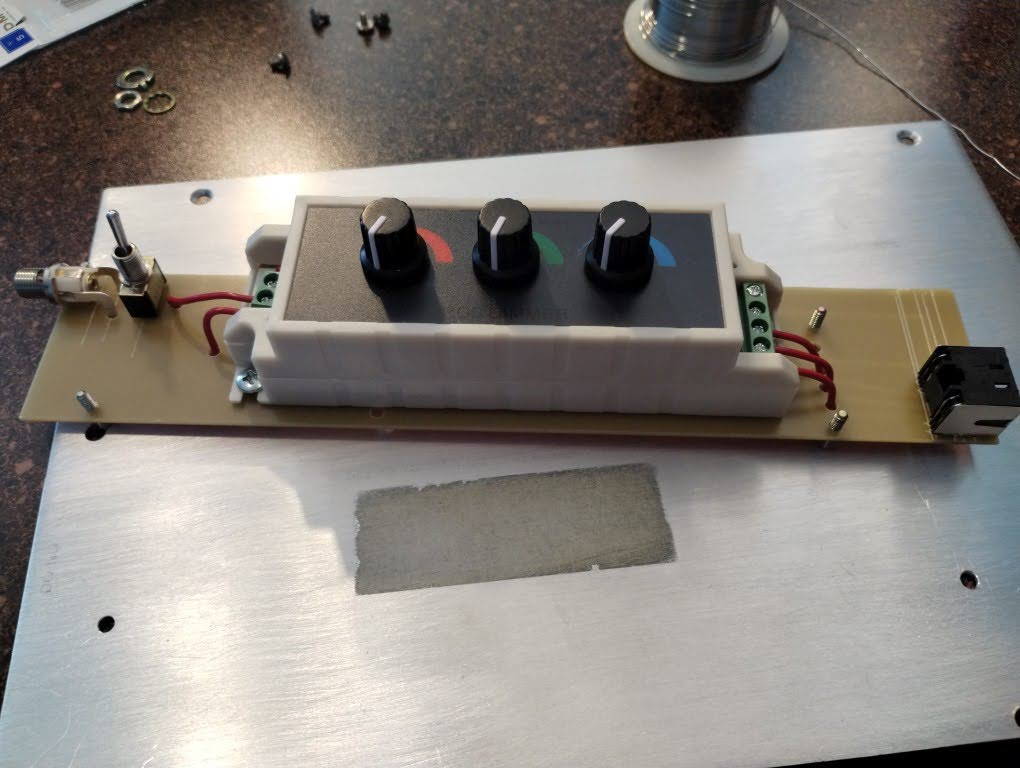
Discussions
Become a Hackaday.io Member
Create an account to leave a comment. Already have an account? Log In.