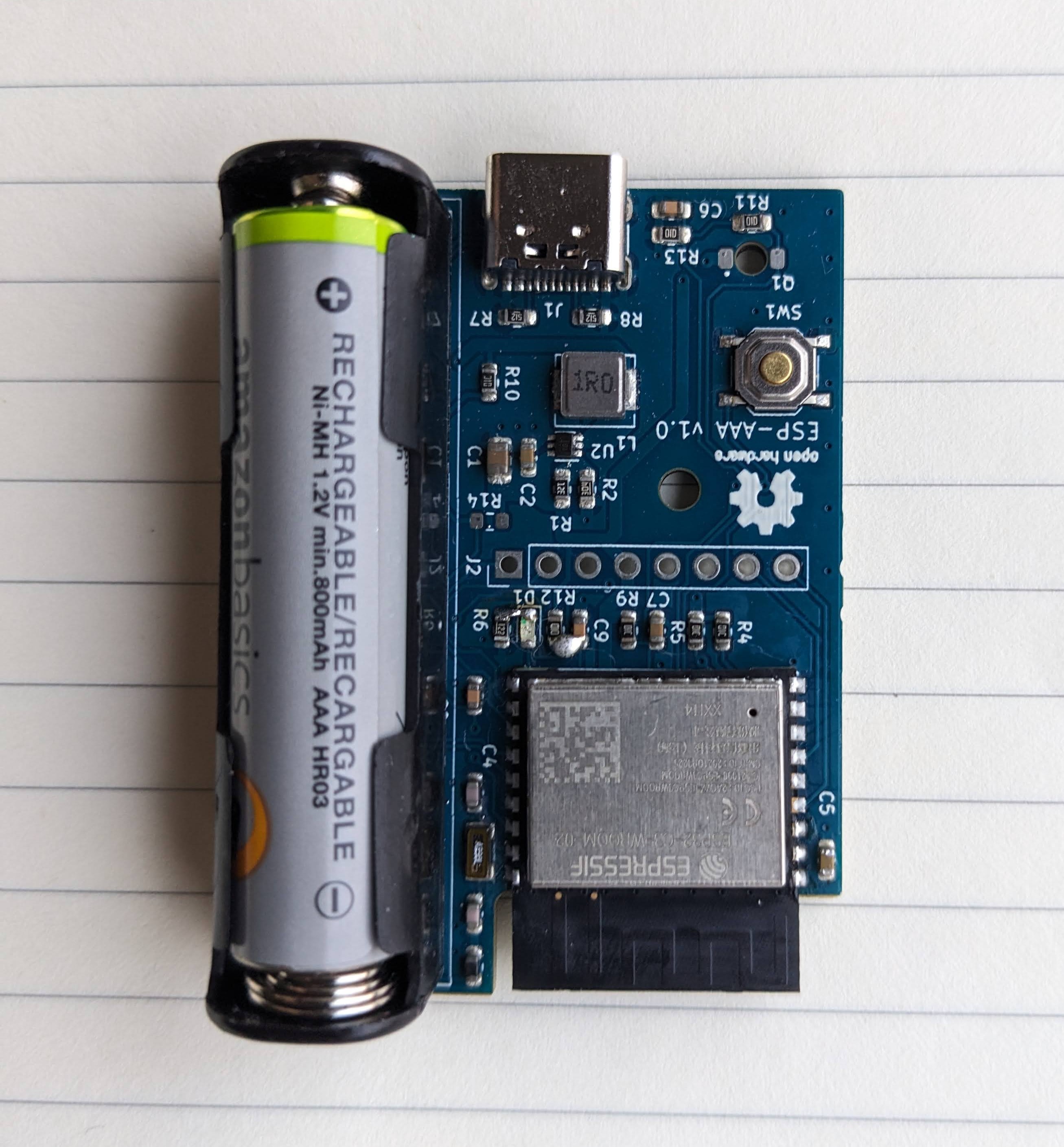
I received the PCBs from JLCPCB which look great, however I have found some issues with the board:
- The TPS61023 boost converter IC I selected will operate down to 0.5V input, but I managed to overlook the point where it states that it requires 1.8V to startup. This means It won't turn on when an AAA cell is inserted. I have found a workaround to continue testing the rest of the board by briefly applying around 2V to the terminals of the cell to allow it to start up, after which it can be removed and the converter will continue to work properly. In a future board revision I will need to use a different IC.
- The pin I selected for the pulse interrupt is not in the RTC domain, for now I will just bridge it to the adjacent GPIO pin which is in the correct domain.
- There were 2 tracks unconnected in the PCB layout, somehow I missed the DRC error, fortunately they were an easy bodge with a blob of solder.
Otherwise the board seems to work, the USB connection for programming works properly.
I have not yet received the phototransistor so that part is not yet tested, but I have flashed an esphome config file and it seems to run as expected.
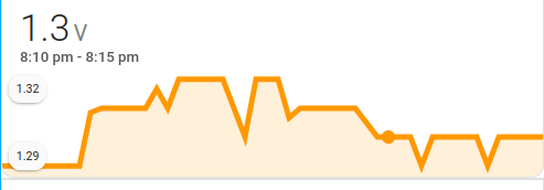
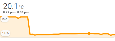
The PCB includes an NTC for temperature measurement, and also a connection for monitoring the battery voltage. Screenshots show the logging in home assistant of the sensor readings over a few hours. The board can also have applications as a battery powered temperature monitor, for locations without grid power such as the loft or greenhouse.

 The current config used for esphome.
esphome:
  name: aaa
  friendly_name: aaa
  on_boot:
    priority: 600
    then:
      - repeat:
          count: 100
          then:
            - output.turn_on: led_output
            - delay: 0.2s
            - output.turn_off: led_output
            - delay: 1s

esp32:
  board: adafruit_qtpy_esp32c3
  framework:
    type: arduino

output:
  - platform: gpio
    pin: 10
    id: led_output

sensor:
  - platform: ntc
    sensor: resistance_sensor
    calibration:
      b_constant: 4419
      reference_temperature: 25°C
      reference_resistance: 100kOhm
    name: NTC Temperature

  - platform: resistance
    id: resistance_sensor
    sensor: source_sensor
    configuration: DOWNSTREAM
    resistor: 100kOhm

  - platform: adc
    id: source_sensor
    pin: 3
    attenuation: 11dB
    update_interval: 10s

  - platform: adc
    pin: 2
    name: "Battery Voltage"
    update_interval: 10s
    unit_of_measurement: "V"
    attenuation: 11dB

deep_sleep:
  run_duration: 30s
  sleep_duration: 10min
 Theo
Theo
Discussions
Become a Hackaday.io Member
Create an account to leave a comment. Already have an account? Log In.