 Shih Wei Chieh
Manufacturing of Large Dye Sensitized Solar Cell at home from Shih Wei Chieh on Vimeo.
Introduction
The main challenge of this research is to integrate multiple cells within a single pair of FTO glass sheets measuring 30 × 60 cm. Dye-sensitized solar cells (DSSCs) are easily manufacturable and cost-effective photovoltaic devices, even feasible at a DIY level. However, their efficiency remains relatively low, posing challenges in meeting commercial standards. This limitation primarily arises from the high sheet resistance of the FTO layer within the system. One of the key advantages of DSSCs is their highly customizable patterns and colors in the transparent TiO₂ layer, enabling aesthetically pleasing smart surface designs that are also electrically self-sufficient. The chemicals used in this experiment were primarily sourced from Greatcell Solar, making most of the fabrication processes conventional, except for the unique cell size used in this study. The measured efficiency yielded approximately 5.8V and 51mA, achieved with 12 cells in a Z-type series configuration and silver traces printed on the counter electrode. Currently the low current output is attributed to the absence of a parallel circuit in this configuration. The next step of this research is to achieve a conversion efficiency close to that of conventional products, which is closely related to the design of the series modules and the layout of the silver wires.

The history of the development of the 3rd generation solar cells.

Schematic representation of a TiO2-based DSSC. DSSC, Dye-sensitized solar cell.
1. Experiment
1.1 Etching the series circuit on FTO glass
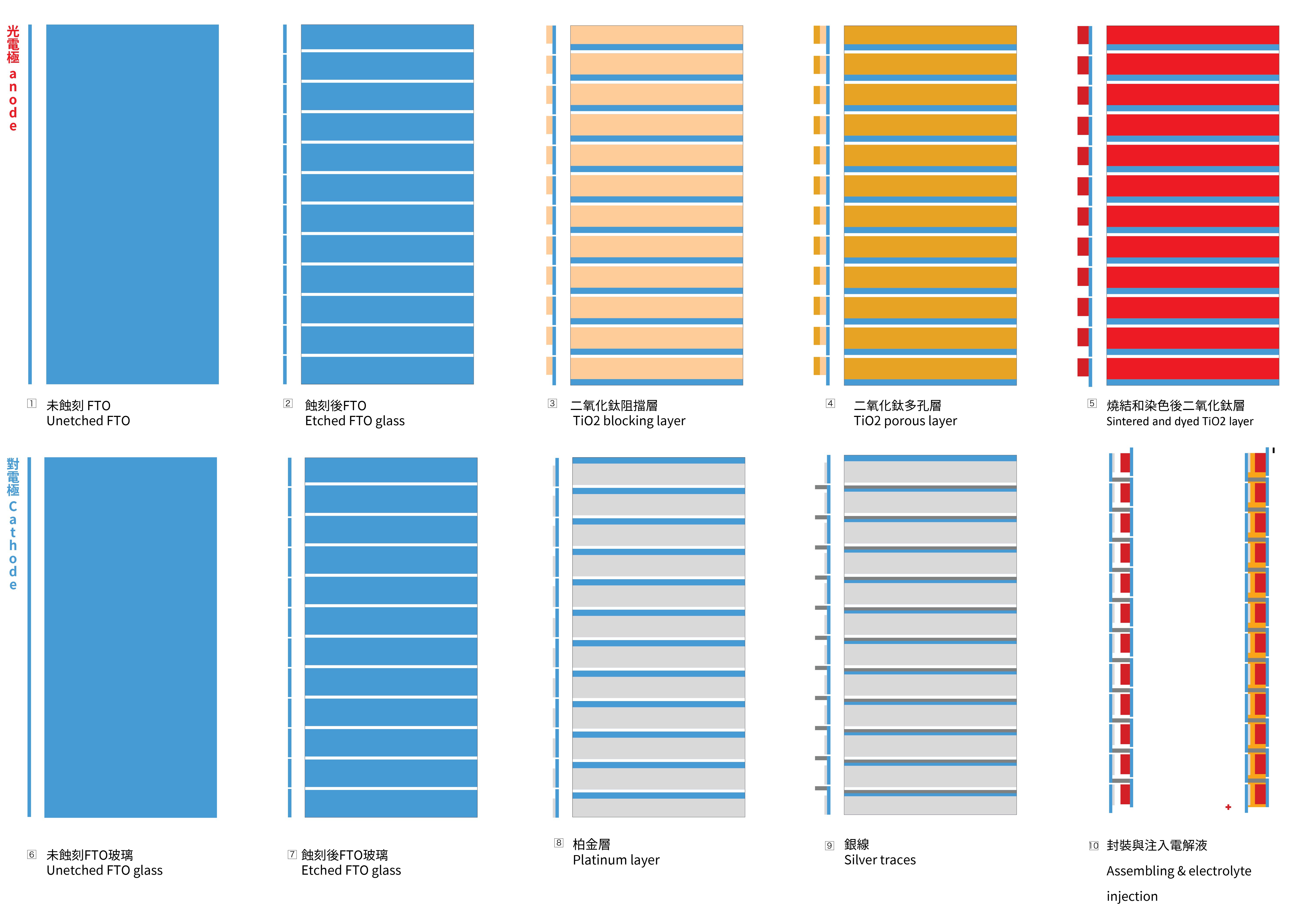
To achieve the necessary voltage, a series circuit is needed to be created with the glass substrates. To achieve this goal, the FTO glass needs to be etched, to create a vertically connection between two FTO glasses. The first picture below illustrates the cross-section of the structure and the positioning of the 12 cells.
About the chemicals employed in this section, firstly, adding 26.3 mL of 38% hydrochloric acid solution to a beaker and then dilute it with water to reach a total volume of 100 mL, to make a 2M HCL solution. The wet photoresist I used here is a product LP8901V6 purchased from Great Eastern Resins Industrial Co. Ltd.(GRECO).

Apply the Kapton tapes to the FTO glass to protect the area wish to be etched. Apply the photoresist to the FTO with glass rod or scraper. Cured the photoresist with UV lamp or sunlight.After the photoresist is fully cured, remove the Kapton tape to prepare for etching. Due to the uneven coating, my result looks ugly here.Use a cotton swab to apply zinc powder to areas that do not have wet film photoresist
Apply the HCL solution with a dropper to the zinc powder. The bubbling indicates the etching reaction is happening.
Wait for 10 minutes to let the etching reaction to be completed. Remove the HCL and zinc powder with tower and water run the board to wash away any left over chemicals.

Immerse the etched FTO in sodium hydroxide solution. After the photoresist is completely dissolved, take out the FTO glass and clean the surface with water and ethanol

Measure the board with multimeter, make sure all 12 conductive strips are completely electrically disconnected.

The successful etched photo-electrode and counter-electrode.
1.2 Sintering of the blocking TiO2 layer and porous TiO2 layer on the photo-electrode
- Apply Kapton tape to the glass to create the mask for the TiO2 layer coating.
- Apply the BL-1 paste with a glass coater. This mask will be shared to make the porous layer later.
- Place the photo-electrode in the kiln, ramping up to 125ºC at a rate of 8ºC per minute without removing the Kapton masks. Maintain this temperature for 30 minutes, and then allow it to cool naturally to room temperature.
- Take the cooled glass out and coat the glass...

 MECHANICUS
 Theresa
 Alfonso Delgado Ollero