 PKvirus
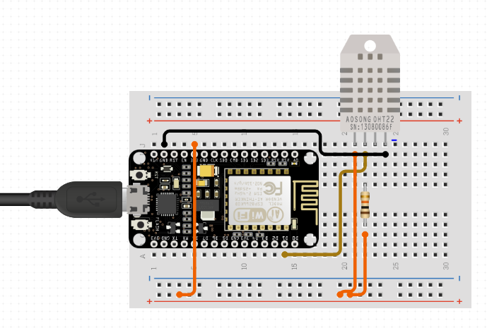
DHT22 Sensor:
- The ESP8266 in the diagram is mounted on a breadboard for easy connection and may be programmed to send the data it gathers from the DHT22 to the Raspberry Pi or directly to the cloud for monitoring.
- It is powered through a micro USB connection, which can be connected to a computer, USB charger, or battery pack.
- This is the main component that controls the sensor and will process its data.
- The data signal pin of the DHT22 is connected to a GPIO (general purpose input/output) pin on the ESP8266 (D1/GPIO5) via an orange wire. This connection is used to transmit the temperature and humidity readings from the sensor to the microcontroller.
ESP8266 Microcontroller:
- The GND (ground) pin on the sensor is connected to one of the GND (ground) pins on the ESP8266 to complete the circuit.
- The sensor's VCC (power) pin is connected to the 3V3 (3.3 volts) output on the ESP8266, providing it with the necessary power.
- The DHT22 sensor has four pins, but only three are used in this setup.
Resistor:
- There is a pull-up resistor connected between the data line and the VCC line of the DHT22 sensor. This resistor is typically around 10kΩ and is necessary for the DHT22 to function correctly, as it ensures the data line is at a defined voltage level when it's not being pulled down to ground by the sensor during communication.
Discussions
Become a Hackaday.io Member
Create an account to leave a comment. Already have an account? Log In.