 tomcircuit
I carefully opened a TI-55 donor unit and inserted a 27ohm resistor in series with one of the digit cathodes. I captured the display sequence on my trusty LeCroy oscilloscope and dumped to the built-in thermal printer - TI-55 LED timing and Vfwd measurement
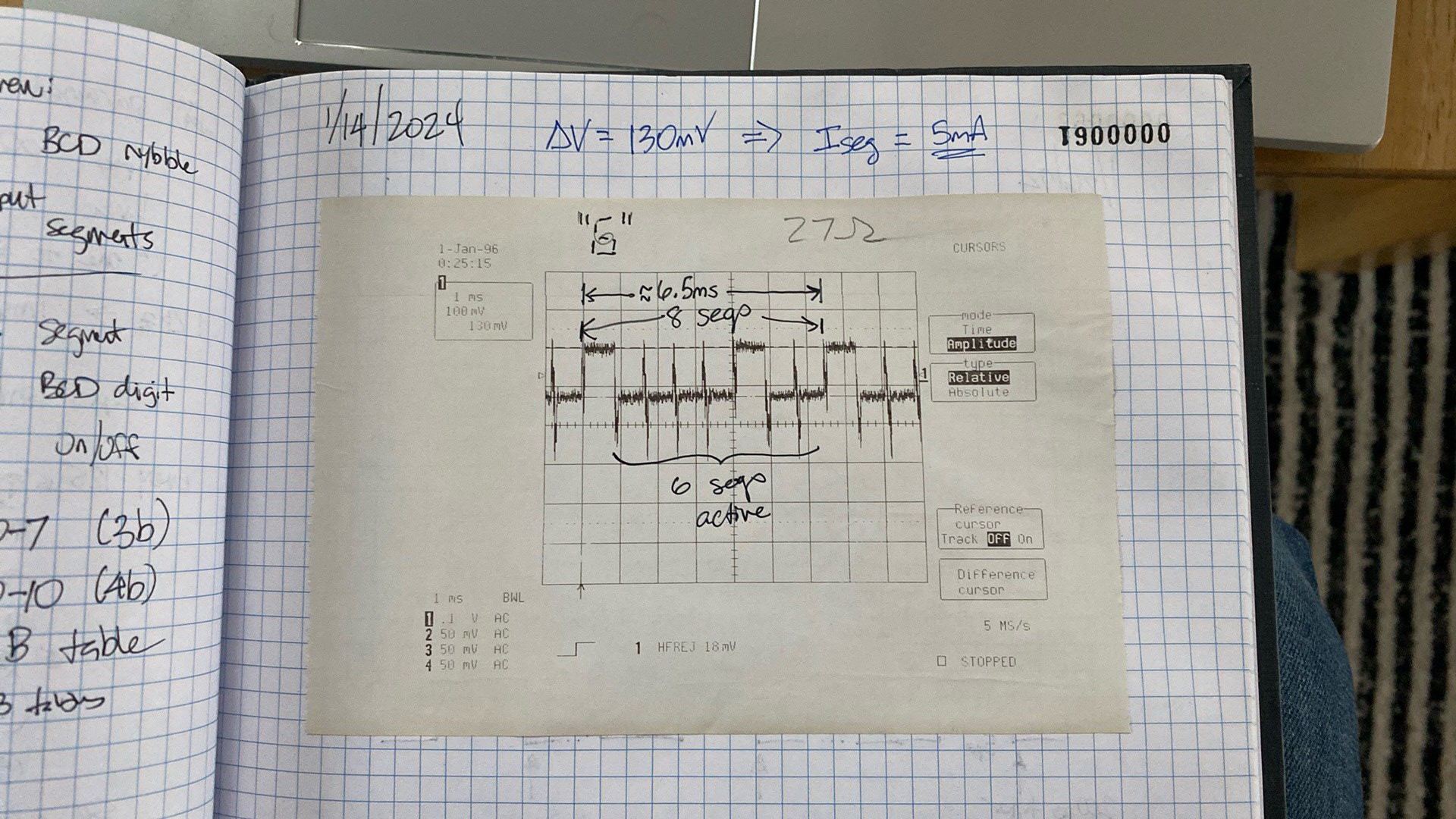
There are several important observations that can be made from this plot:
- The LED is scanned by segment rather than by digit. That is, all of the "a" segment anodes are sourced, but only the digit common cathodes in the digit positions that have this segment illuminated are sunk. This means that the TMC1500 has only to 'scan' 8 segments (a-g, dp) rather than the more intuitive approach of scanning 12 digits. This is covered in TI patent Number 4,014,012 so was not a surprise to me.
- During a display cycle, each segment anode is energized for 800us, and the overall display cycle duration is 6.4ms. TI patent Number 4,125,901 describes how, during a display cycle, the CPU cycle interval is increased by a factor of 32, so that the LED display is visible. This implies that the normal CPU cycle interval is 6.4ms / 32 = 200us.
- The voltage across the 27 ohm series resistor I fitted to one digit's common cathode, when energized, is 130mV. Therefore, the segment current is 5mA. If all 12 digits have the same segment active, the segment driver must source 5mA * 12 = 60mA. This is a bit much for a single MCU GPIO output pin, so PNP BJT or P-MOS will be required for each segment line. On the other hand, each digit has only one segment active at any one time, so the most current the digit drivers must sink is 5mA.
Thank you, TI-55. That didn't hurt a bit now, did it?
Discussions
Become a Hackaday.io Member
Create an account to leave a comment. Already have an account? Log In.
I guess it saved them some ICs. I remember that the early one chip calculators needed driver ICs. One drawback is the need to have displays where all the corresponding segments are wired together rather than all the segments of a digit. But then TI also made displays at the time so no problem.
Are you sure? yes | no
Ah, here it is - the PMOS for segment drive has its source connected to VSS (+9V) so it's a good high side anode driver, able to handle multiple anodes simultaneously. The PMOS for digit drive is more of a "source follower" configuration so it's much happier sinking a smaller amount of current. This is described well in column 4 lines 17-52 of the patent text. Of course, a Common Anode display would be back to "digit scanning" vs. "segment scanning".
Are you sure? yes | no
The patent hints at some advantage to segment scanning and integration. I can only imagine that it has to do with PMOS source drivers for the segments, versus lateral PNP sinks for the digits. But, then, just go from Common Cathode to Common Anode configuration. I agree that the 12.5% duty vs 8% duty is an advantage. Another thought: perhaps TI had to go with segment scanning because someone else patented digit scanning? There’s a whole TI patent devoted to a 3-bit counter that counts in an unusual sequence 4,277,675, and for the life of me I can’t fathom what purpose this serves!
Are you sure? yes | no
Not sure what the advantage of muxing by segment is compared to muxing by digit. I suppose it limits the duty cycle to no less than 12.5%.
Are you sure? yes | no