 Craftiarenko
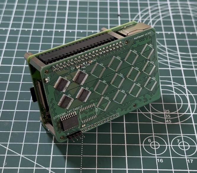
Tested the first version of the board.
Found a few errors:
1. Missed route
2. Activation of the MUX without an address leads to a short circuit of the zero pin
3. The voltage drop on the Darlington array is too high
Conclusions: soldering the board to the end does not make sense, it is necessary to fix the PCB
Discussions
Become a Hackaday.io Member
Create an account to leave a comment. Already have an account? Log In.