 schuyler4
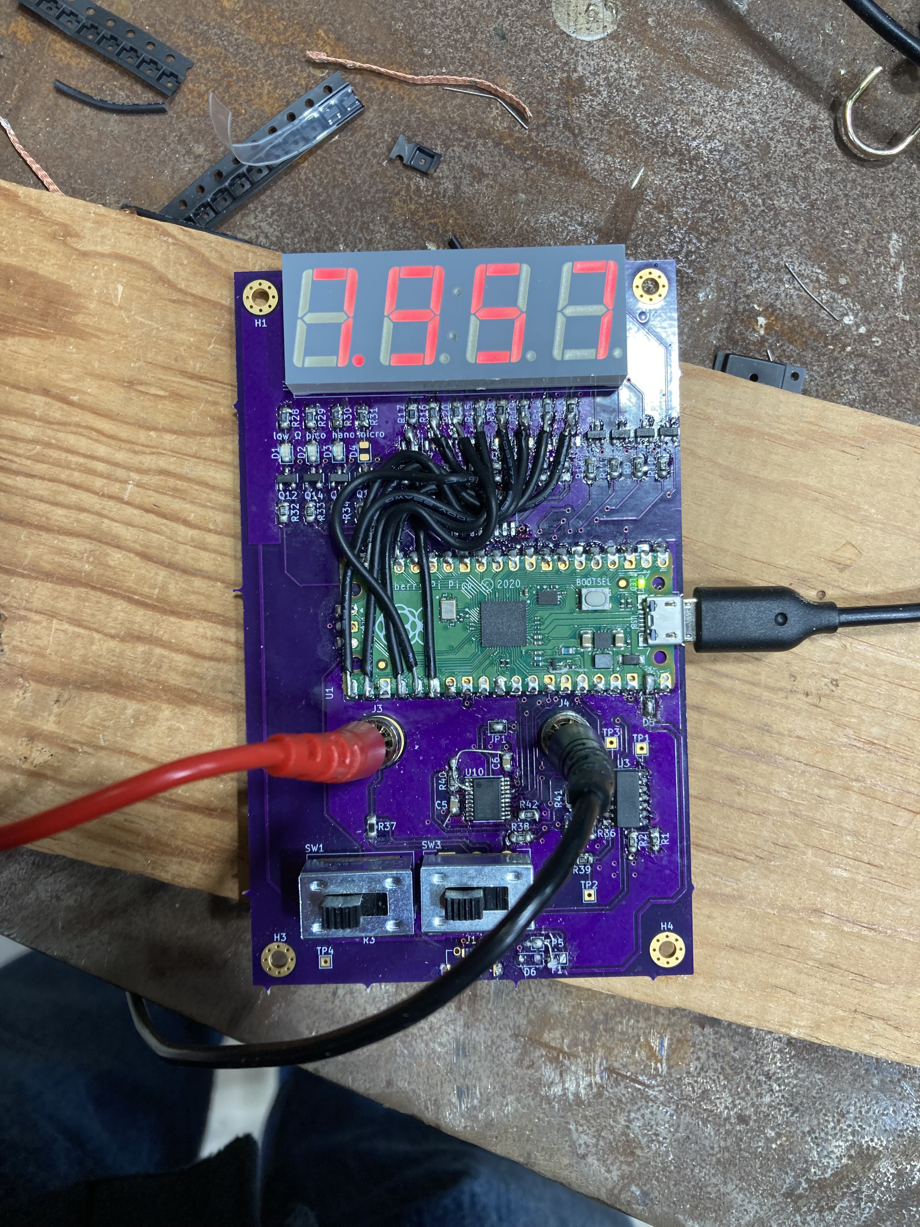
To make the display work on revision 1, I bypassed the display driver and wired the pico IO pins strait to the segment LEDs. It is a little faint, as the display driver circuit worked completely differently, but it works to test the display.
A project log for Multimeter
This is my homebrew multimeter design. Included modes are VDC, Ohms, and Capacitance.
To make the display work on revision 1, I bypassed the display driver and wired the pico IO pins strait to the segment LEDs. It is a little faint, as the display driver circuit worked completely differently, but it works to test the display.
Discussions
Become a Hackaday.io Member
Create an account to leave a comment. Already have an account? Log In.