Close
0%
0%

Relay Computer

Clickity-Clackity Goodness

Similar projects worth following
I've wanted to build a relay computer since forever. My backplane and card design is heavily influenced by the S-100 era (Altair/IMSAI) to make it a plug-n-play machine. The architecture is based on that of Dr. Harry Porter, although I'm going to take some cards in a different direction because...why not?! And I'm using an Arduino to do some automated testing along the way.

This relay computer project is based on the designs of Dr. Harry Porter, who designed and built a multi-wall sized fully functional relay computer at Portland State university.  Dr. Porter was gracious enough to share much of his designs which can still be found on the internet. I've also been leveraging the work of Paul Law, who built a relay computer based on Dr. Porter's design, and he shared much of his design in detail. Most of the popular relay computer designs owe a debt of gratitude to Konrad Zuse who built the first relay-based computer (with 2600 relays) by 1941. 

When we say relay "computer" - it's more like relay "central processing unit".  The architecture is as follows:
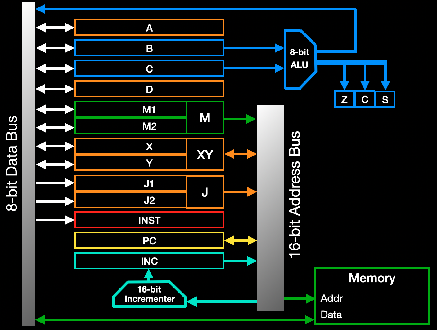
The A - D registers are 8 bits, and then we others like M1 + M2 that can be combined to a 16-bit M register. These 16-bit ones are used to leverage addresses for jumping or returning to specific memory locations. 

So to make a working clickity unit, we'll need:

  • A 16-bit incrementer
  • 16-bit Program Counter
  • Some sort of memory to hold the code
  • An Arithmetic Logic Unit (ALU) to do some math stuff
  • A whole bunch of registers
  • An 8-bit data and 16-bit address bus to tie it all together

  • My First Register

    DiPDoT (Brian)12/10/2024 at 01:06 0 comments

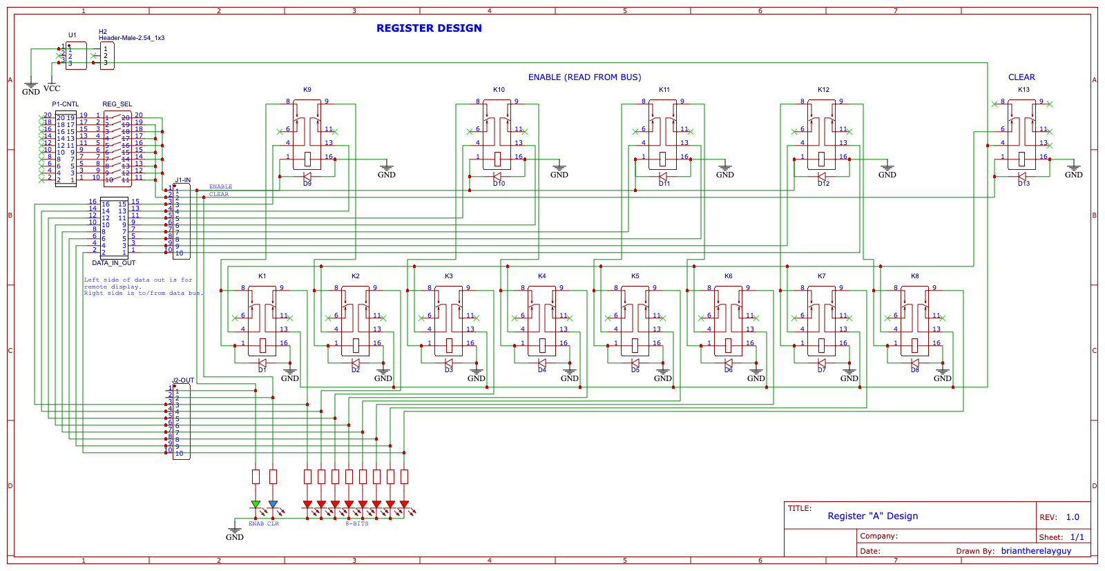
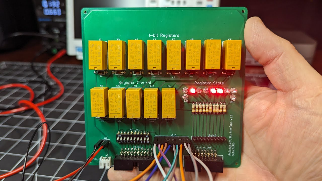
    My journey started with breadboards and a bunch of DPDT relays I ordered from Amazon. But since a prototype board can only hold 7 relays comfortably, I soon realized I'd need to use some other forms to put it all together.  I tried using hole pad boards, but ultimately jumped to using PCBs, and created my first register design.

    ...which became this...

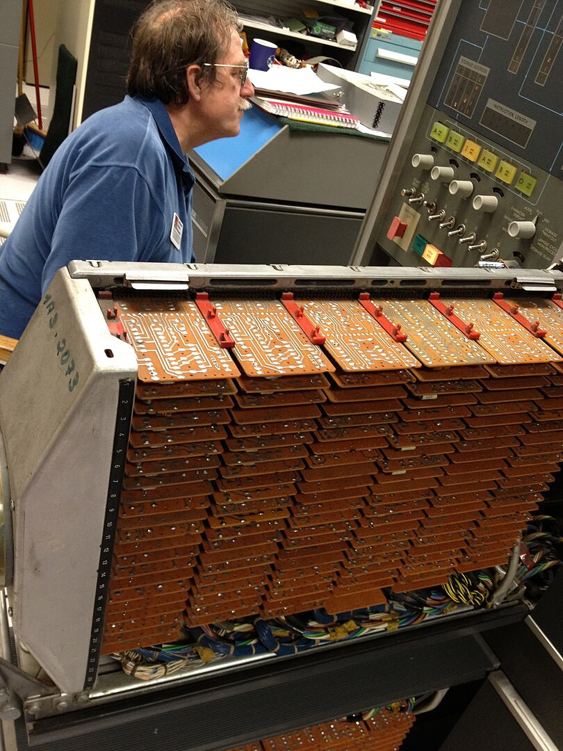
    This was my first PCB, and although I was very proud of it, I almost immediately noted that if I was going to need around 15 of these, that was going be a lot of wiring and ribbon cables. I also wasn't happy with the need to send a control signal to clear the register before loading it. Fortunately, Dr. Porter had designed a self-clearing register design, and as for the cables...well...I got my inspiration while watching a video about the IBM 1401 - and it's beautiful card cage!

    So if I'm going to go with an edge-card, I'll need to know...how many pins will I need?

View project log

Enjoy this project?

Share

Discussions

Similar Projects

Does this project spark your interest?

Become a member to follow this project and never miss any updates