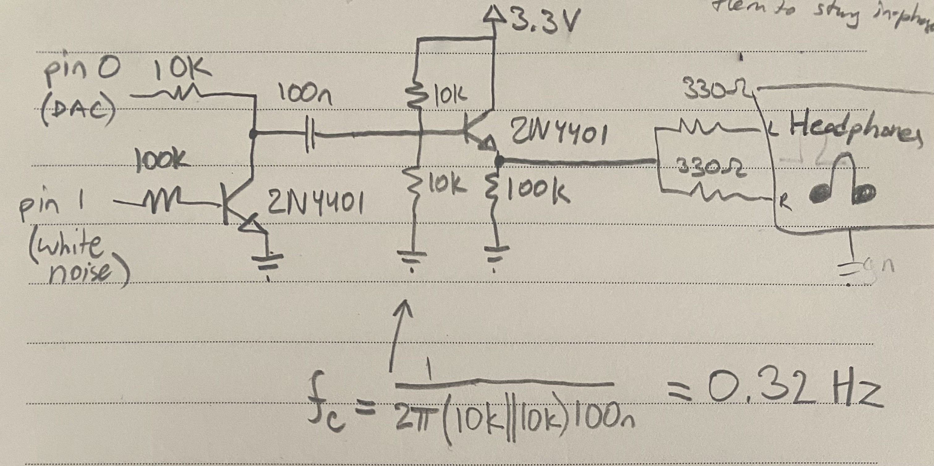
Today I programmed the DAC on my Seeeduino XAIO SAMD21 to output a slow triangle (ish) wave and used that signal to modulate the amplitude of the white noise. I used a swing-type VCA as shown below, which is rarely used because it heavily distorts (clamps) the input signal, but in this case the input signal is already a square wave so its perfect for this application. I coupled the output through a capacitor, and biased the input transistor at half the rail voltage (written 3.3, but its actually 5V from the USB-C cable, pin 14) Honestly, after looking at it again I don't think this is optimal nor necessary, I could've just buffered it straight and coupled the output to the headphones. Also right now, the output to headphones would be floating around 2.5V, and the headphones ground is 0V, so there will be a hefty DC bias on the headphones, which may not be ideal. I didn't head any pops or clicks when connecting though, so maybe its ok. Improvements needed, but it works.
Next time I will try improving this circuit and improve the Arduino code as well. I'm thinking of making 2 pink noise sources (Waves R+L) and 2 white noise sources (wind R+L), meaning 4 amplitude CVs, so I will need to try PWM CV instead of DAC. WInd source should reach around 4Hz for details but otherwise around 10-20s period. Waves around 10s period with a little swell shape __...-~-...__
uint8_t downscale = 2;

// Called in timer ISR, around 93KHz
void do_analog() {
  static int8_t delta = +1;
  static uint16_t y = 0;

  y += delta;

  if(delta == +1 && y == (1 << (10+downscale)) - 1) {
    delta = -1;
  } if(delta == -1 && y == 0) {
    delta = +1;
  }

  analogWrite(0, y / (1<<downscale));
}
Discussions
Become a Hackaday.io Member
Create an account to leave a comment. Already have an account? Log In.