 DiPDoT (Brian)
How it started...
I started this project with a fully functional TRS-80 Model II, including the stock keyboard. The first thing I did was get a copy of the TRS-80 Model II Technical reference manual to grab as much info as possible about the keyboard interface.


Next I intercepted the keyboard interface output lines directly from the keyboard card:
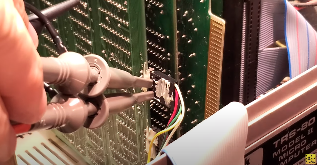
And captured the keystroke on the scope:

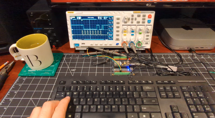
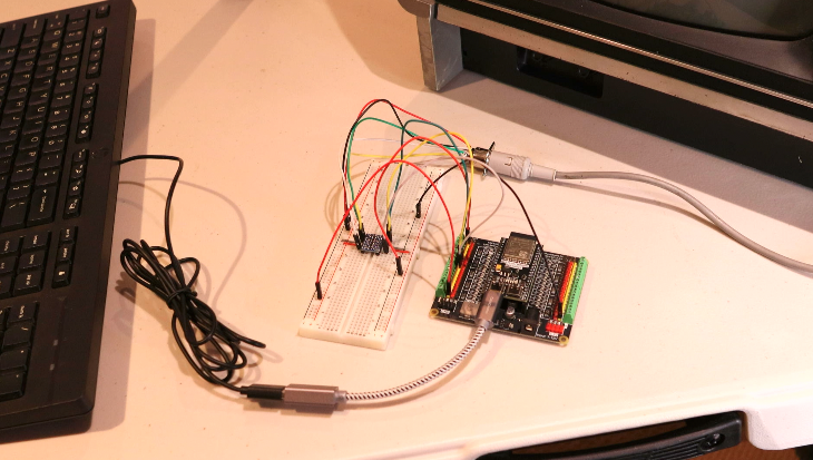
Then it was time to hookup the Arduino to enable some bit-banging:

Originally, I started writing the code literally from scratch, including the shaping of the waveforms themselves. Who knew that there was already a very handy ShiftOut function in the Arduino library? (Not me, that's who!) 😉 Fortunately I did some learning and was able to get a matching DATA and CLOCK signal that was (almost) perfect!

I later figured out (through trial and error) that the double characters were from push the signals through too quickly. Once I slowed it down to "typing speed" it seemed to clear up that problem.
USB Host Ghost
This is where things got weird. I purchased an Arduino compatible USB Host Shield from Amazon. The build quality was "ok" but I couldn't get it to work. After scouring several forums (and soldering the appropriate power jumpers) I found out that there's known issue with the wrong driver chips being used on these boards...the only fix was to replace one of them - they are surface mount - I don't have the tools, skills...or maybe just the patience...time to go in another direction!
Enter the ESP32
I made the switch from Arduino to ESP32, more specifically the ESP32 S3 WROOM. I also moved to the Visual Studio Code IDE. It took a few evenings to get the hang of it...I'm still an Arduino fan but this ESP32 is powerful stuff indeed!
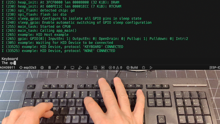
A couple of evenings in and I was already able to get the ESP32 to process USB HID keystrokes...I was on my way again!!!
I ported my old Arduino code over to the ESP32, and managed to produce a duplicate of what the TRS-80 Model is looking for. (Note that M2_USB_Keyboard.c code is attached to the project for download.)
/**
 * @DiPDoT - NEW M2_SHIFTOUT FUNCTION used to bitbang the DATA and CLOCK
 *
 * @params: dataPin  : GPIO of DATA
 *          clockPin : GPIO of CLOCK
 *          bitOrder : MSBFIRST or LSBFIRST
 *          val      : Output Key Code (ASCII)
 */
/**
 * @DiPDoT - NEW M2_SHIFTOUT FUNCTION used to bitbang the DATA and CLOCK
 *
 * @params: dataPin  : GPIO of DATA
 *          clockPin : GPIO of CLOCK
 *          bitOrder : MSBFIRST or LSBFIRST
 *          val      : Output Key Code (ASCII)
 */
void M2_shiftOut(uint8_t dataPin, uint8_t clockPin, uint8_t bitOrder, uint8_t val) {
    uint8_t i;

    // Model II - Only send the value if the busyPin is HIGH
    if(gpio_get_level(BUSY_PIN)) {

        // Model II - Start DATA high (Don't know if this is needed but just matching the spec for now)
        gpio_set_level(dataPin, HIGH);

        for(i = 0; i < 8; i++) {
            if(bitOrder == LSBFIRST)
                gpio_set_level(dataPin, !!(val & (1 << i)));
            else
                gpio_set_level(dataPin, !!(val & (1 << (7 - i))));

            ets_delay_us(SO_DELAY);         // Stalls execution for #uS
            gpio_set_level(clockPin, HIGH);
            ets_delay_us(SO_DELAY);         // Stalls execution for #uS
            gpio_set_level(clockPin, LOW);
            ets_delay_us(SO_DELAY);         // Stalls execution for #uS
        }

        // Model II expects line to be high
        gpio_set_level(dataPin, HIGH);
        ets_delay_us(SO_DELAY);         // Stalls execution for #uS

        // Add the "notch" to the end of the data cycle
        gpio_set_level(dataPin, LOW);
        ets_delay_us(SO_DELAY);         // Stalls execution for #uS
        gpio_set_level(dataPin, HIGH);
    }
}
Because the ESP32 has a max input of 3.3V to the GPIOs, I also needed to use a bi-directional level converter. Fortunately these are cheap and plentiful, and I was almost ready for the big test!
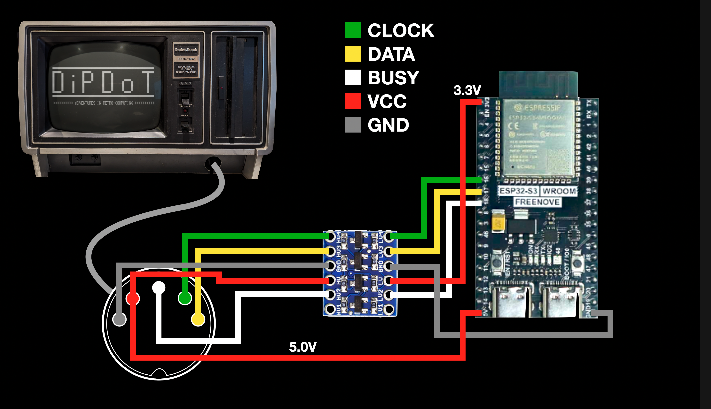
I used a female DIN connector this time so I don't even need to pop the top off of the Model II.
Testing
The new board is capturing keystrokes and bit-banging them to the Model II perfectly! I haven't seen a single double character...
Read more »
 Sumit
Sumit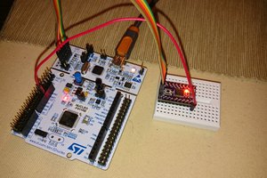
 Christoph
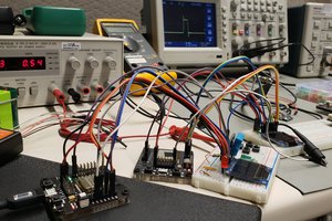
 David M.
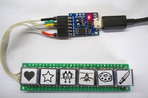
 danjovic