Got my AMC130M03 eval board from oshpark. Assembled the board and...yippee - it worked.
Here is the setup on the bench. I ran extension cords from walls plugs that were on different lines (i.e., L1 and L2) from my house mains. The extension cords plug into the resistor chain voltage divider. It has 5x100k resistors, and then 1k resistor to neutral (so, V_out = V_in * 1k/(1k + 500k)). The reduced voltages are fed to ADC0 and ADC1 of the AMC130M03.
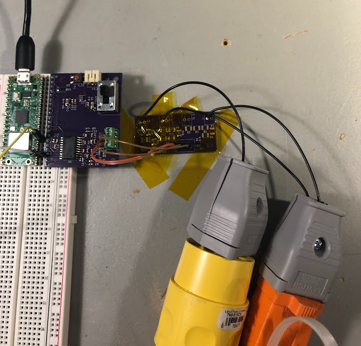
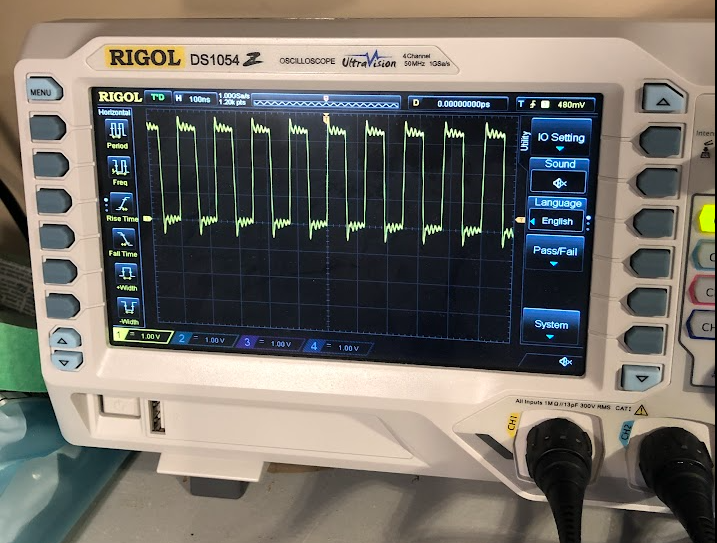
The AMC130M03 has an isolated DC-DC converter that you feed a 8 MHz signal to. So, I created a PIO on the pico that outputs the 8 MHz tone.
After programming the AMC130M03 through the SPI, I can then capture ADC samples every millisecond from the L1 and L2 voltages. From the ADC samples, you can calculate the actual voltage knowing the PGA gain of the AMC130M03, and the resistor divider, so you get the plot below.
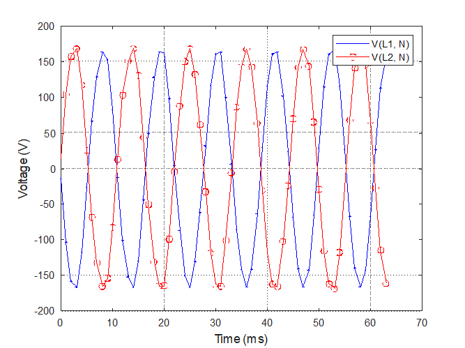
Each line is ~170 V peak, and the two lines are out of phase as expected, joy!
So, now I can measure high voltages with an isolated ADC! The full scale range of the ADC is +/- 1.2 V, so +1.2 V with the voltage divider would be 601.2 V, so plenty of range for the Camry pack voltage (expected to be around 300 V).
Discussions
Become a Hackaday.io Member
Create an account to leave a comment. Already have an account? Log In.