Working on the custom DC to DC converter. I made an EVB for the LT3751. This board will take 12V from the battery, and convert to 245V to charge up the high voltage battery in the Camry.
Here is the board built up on the bench. The main inductor is a Wurth 750341145, and the transistor is a SIJH5800E-T1-GE3. I set the maximum current to 2A using a 0.05 Ohm sense resistor. The feedback to set the output was 3, 200k 1206 resistors in series, and then the divider resistor was 3k to ground (i.e., 245 V * 3k / 603k is 1.21 V). The high voltage rectifier was a wolfspeed silicon carbide C3D04060E.
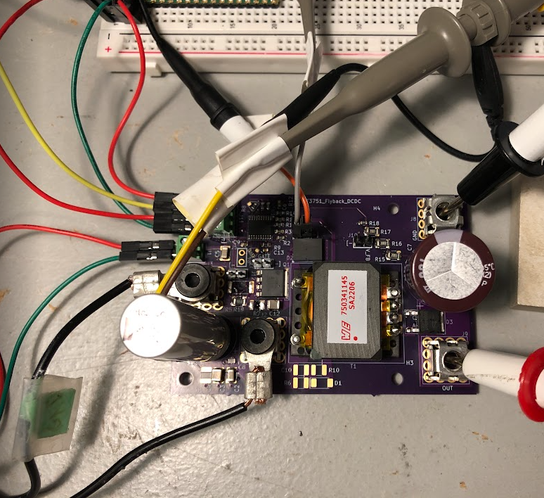
Because the transformer is only 1:5, the VDS expected is approximately 12V + (245V / 5) or 61 V at the highest during the switching. I'm going to look at the Wurth 750310355 transformer (1:10) so the max VDS isn't so high.
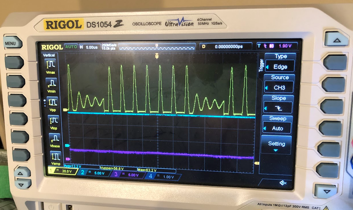
Here are a few traces on the scope. Ch1 (yellow top) is the VDS. It reaches up to ~63.2V. The input 12V seems to be holding up monitored on Ch2 (blue, middle), and the fault seems to be okay on ch3 (purple, bottom).
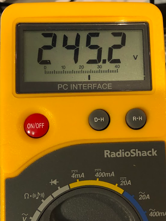
Lastly, the basic DC meter at the output, 245 V! Yippee.
Discussions
Become a Hackaday.io Member
Create an account to leave a comment. Already have an account? Log In.