 Quinn
QuinnVarious logs about the Synths
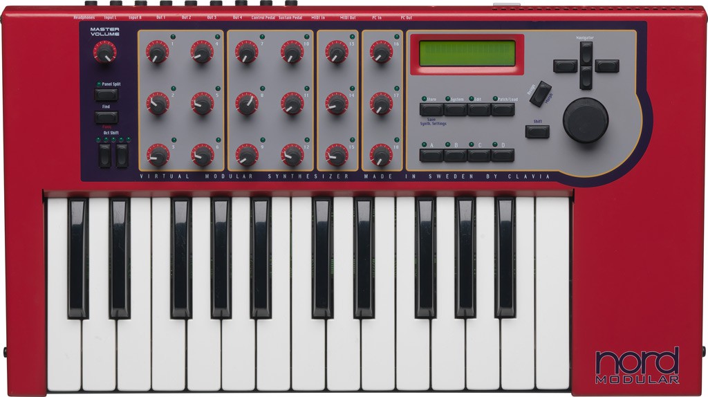
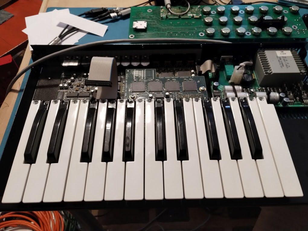
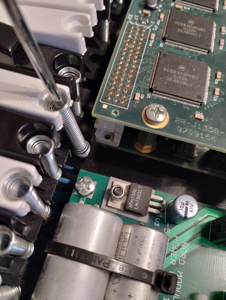
Nord Modular Key (G1)
This is the first generation Nord Modular, key version(as opposed to rack or micro modular version). It is a DSP based analog modeling synthesizer which models modular synthesizer modules. Design and patching is done on computer software, transfered live over a bidirectional control MIDI link. Panel knobs, keys as well as external inputs and outputs are linked with the virtual modules in the software. This one has the original Nord expansion board, which enables additional polyphony.
The software is solid, though retro given the 1998 era of the synth. Windows and Mac OS 8/9 are officially supported, Mac OS X is unofficially through a beta version, and there is a third party Linux version as well.
The control MIDI link is picky on the MIDI adapter as it uses modes which are not supported on the cheaper adapters. I ended up using a Roland UM-ONE MK2 as a cheap one didn't work. The official Nord Modular manual basically says if it doesn't work, try a different adapter, less than ideal.
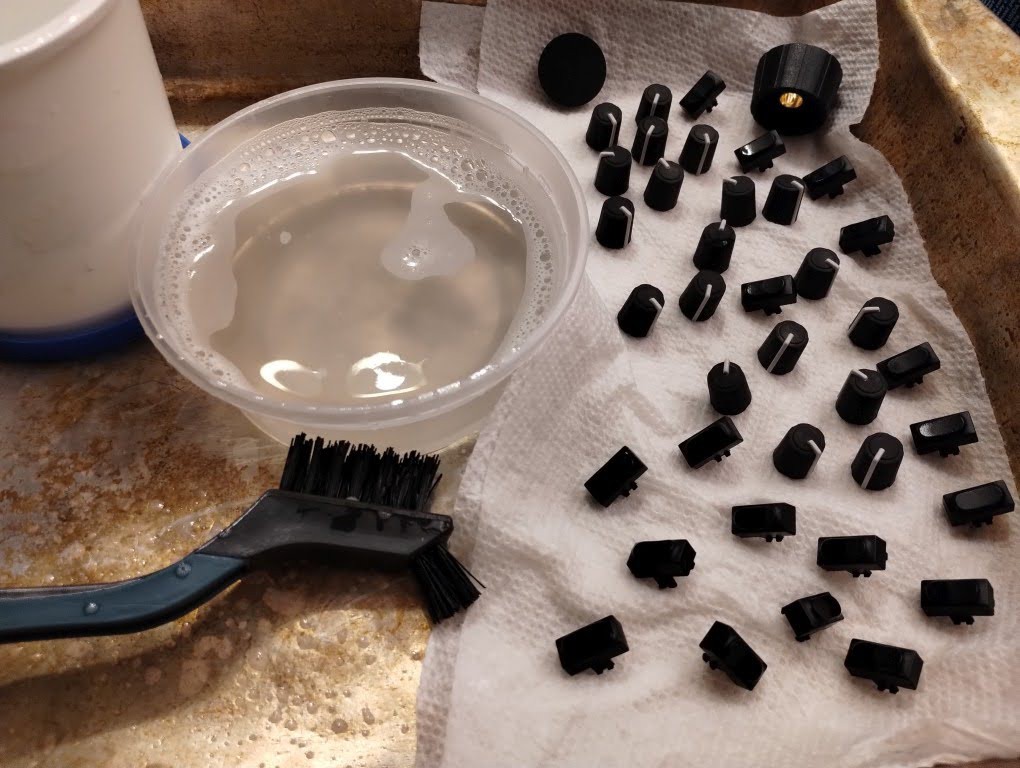
No true repair was needed on this, just restoration.
Project Logs
Ongoing logs:
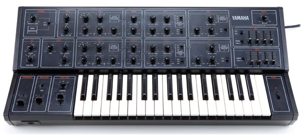
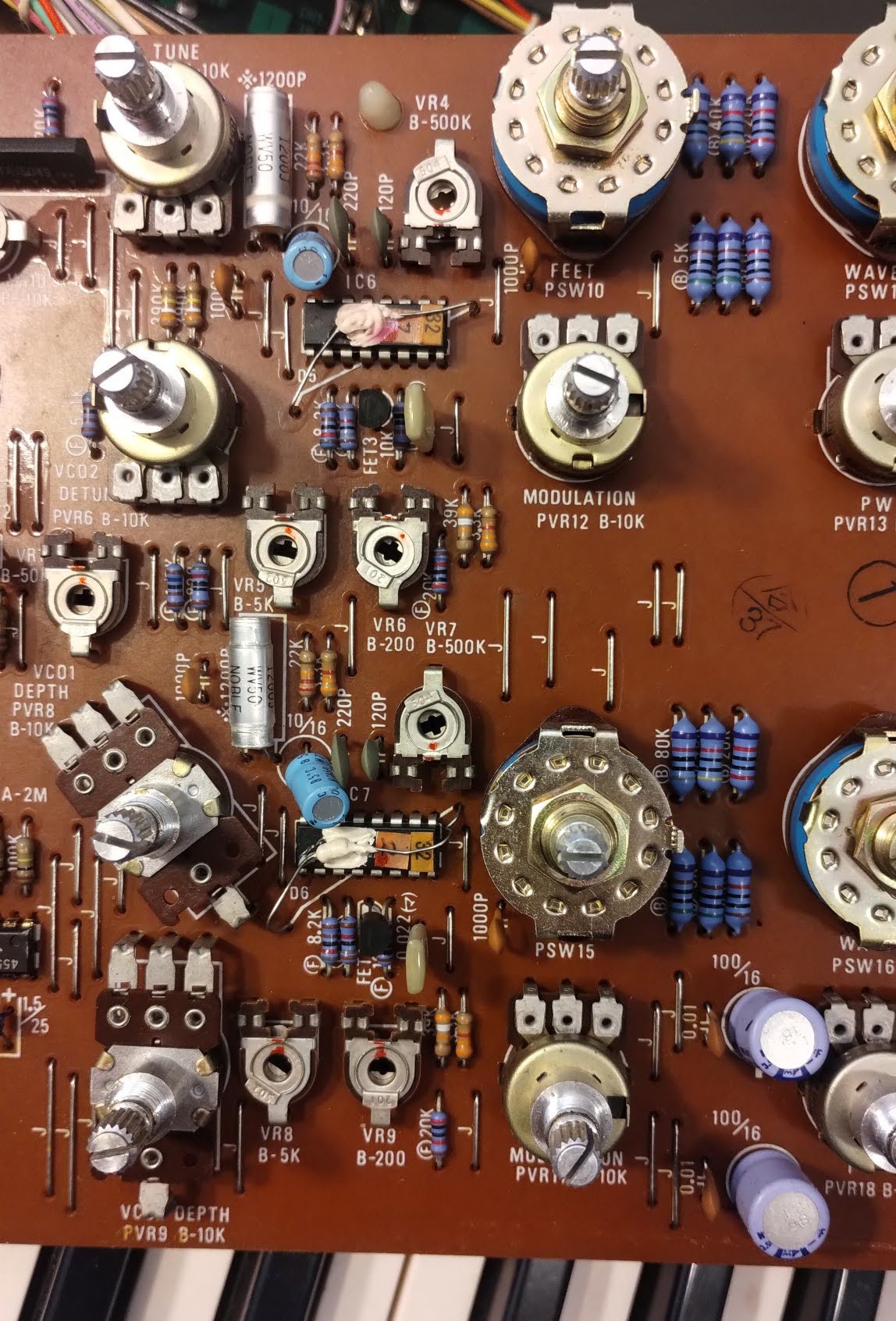
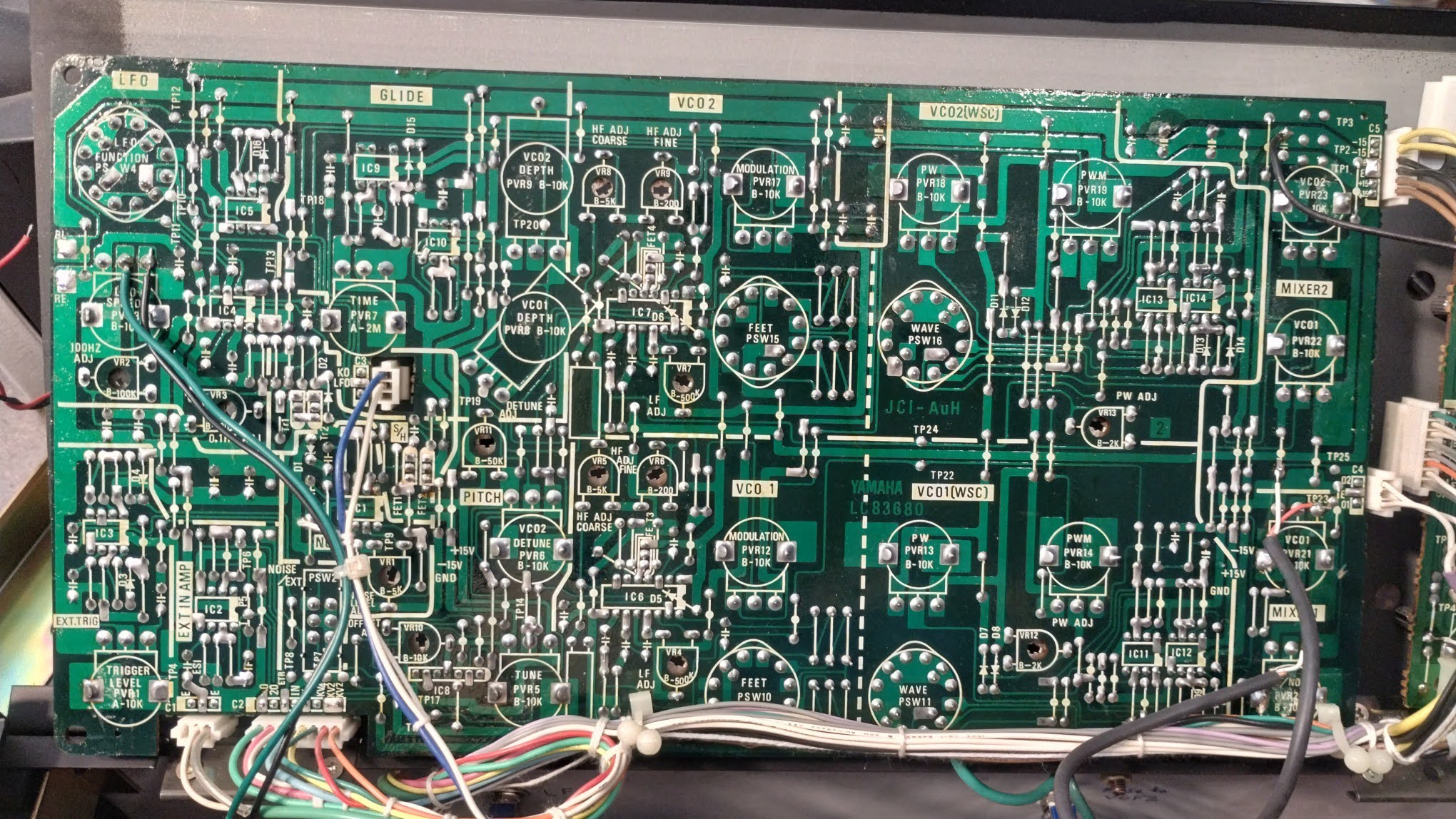
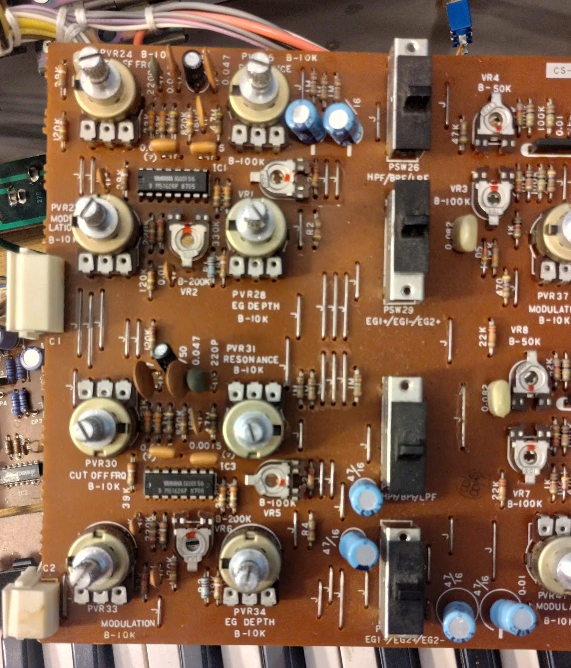
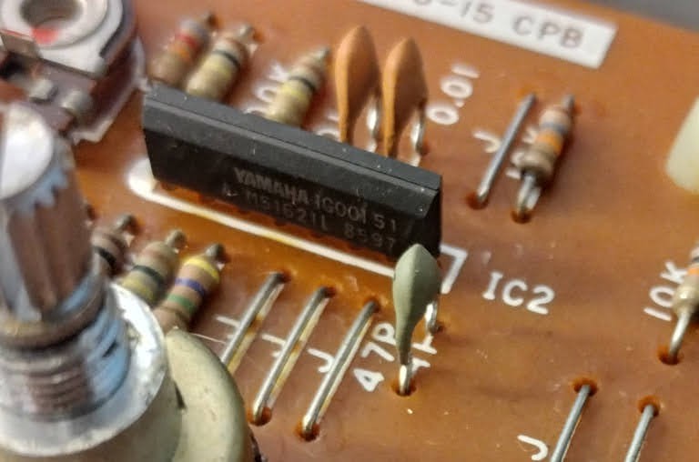
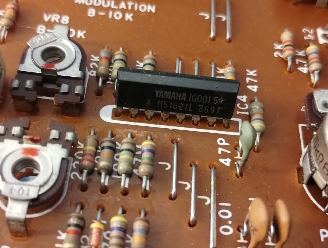
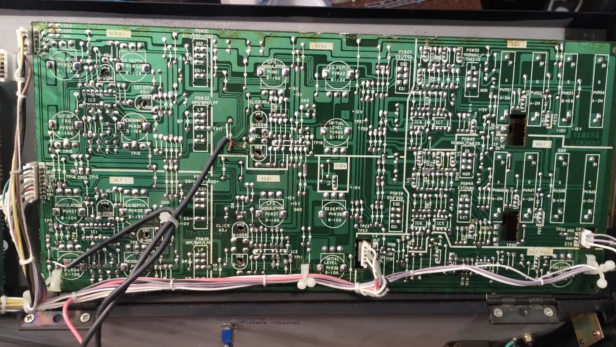
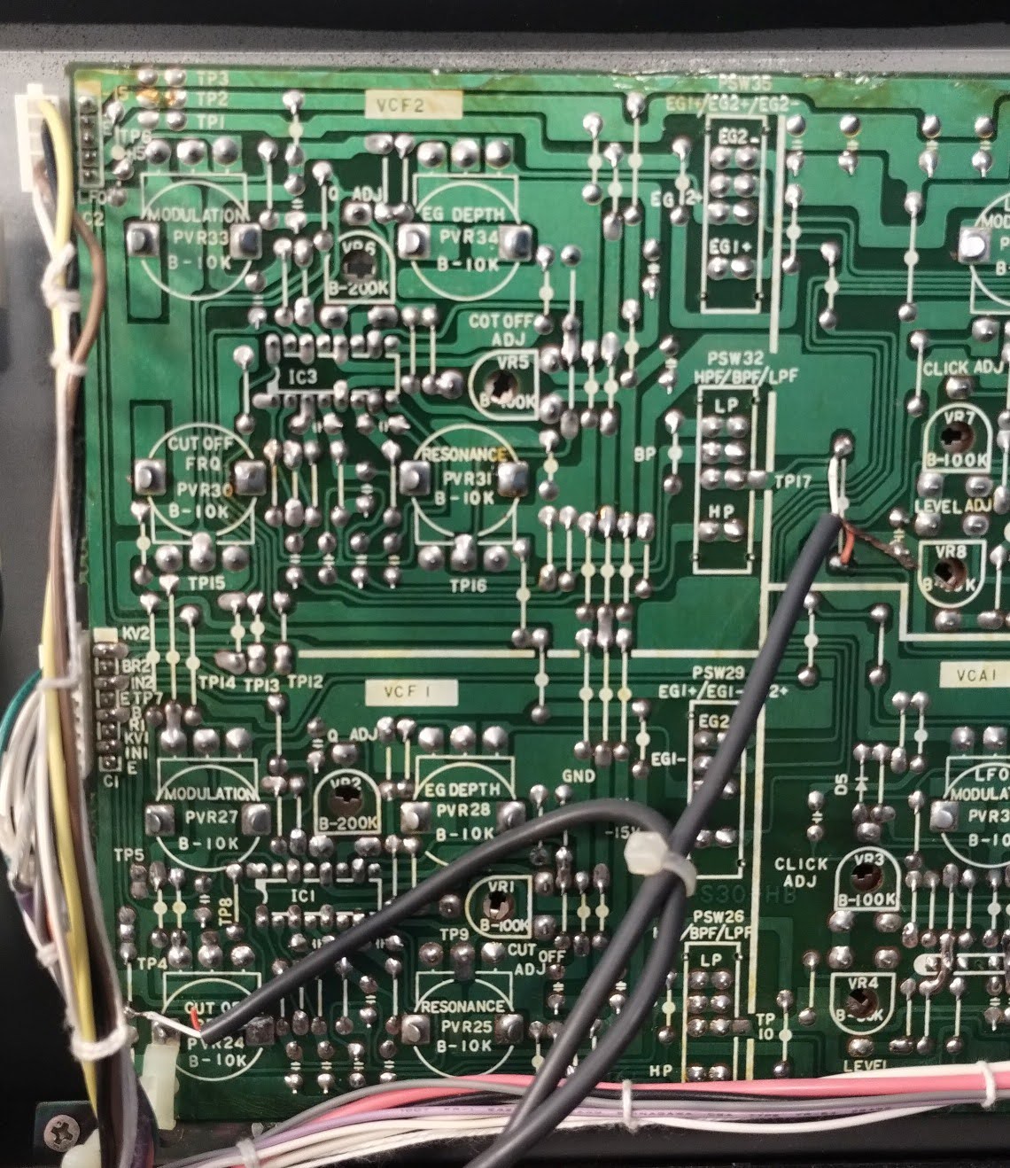
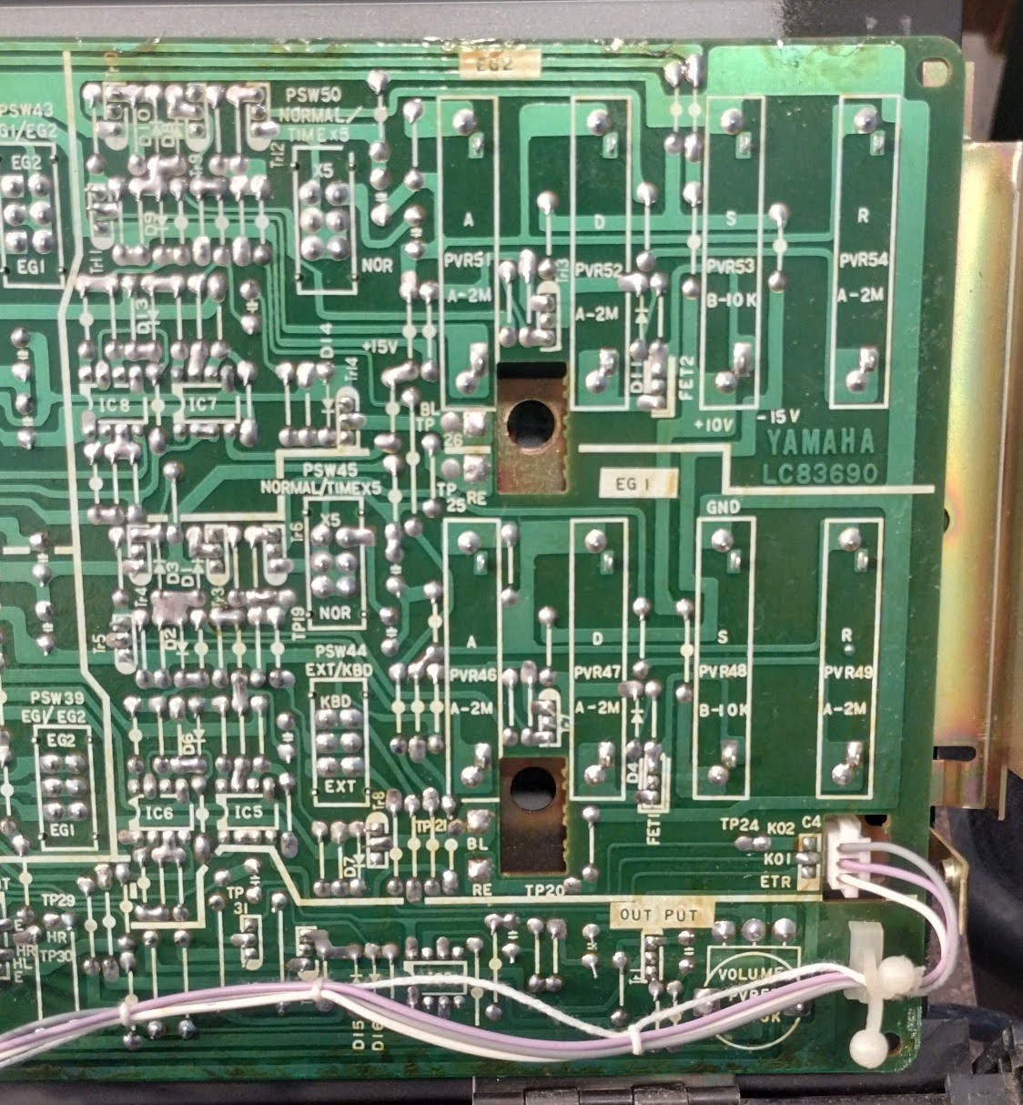
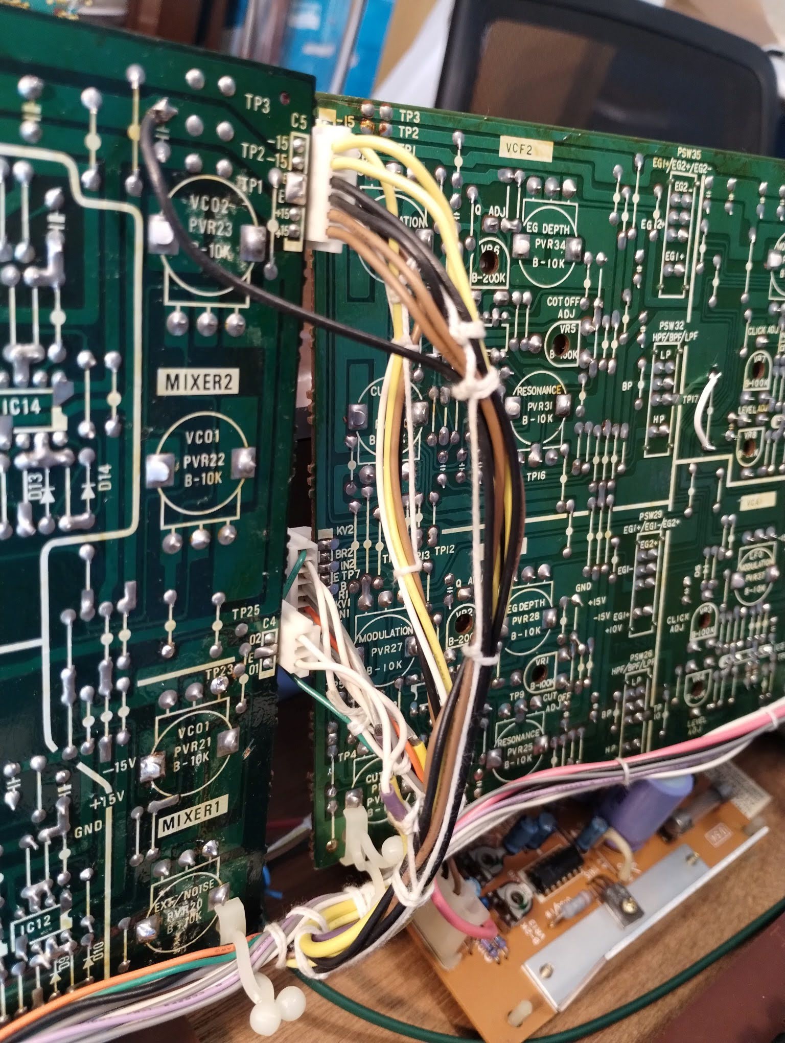
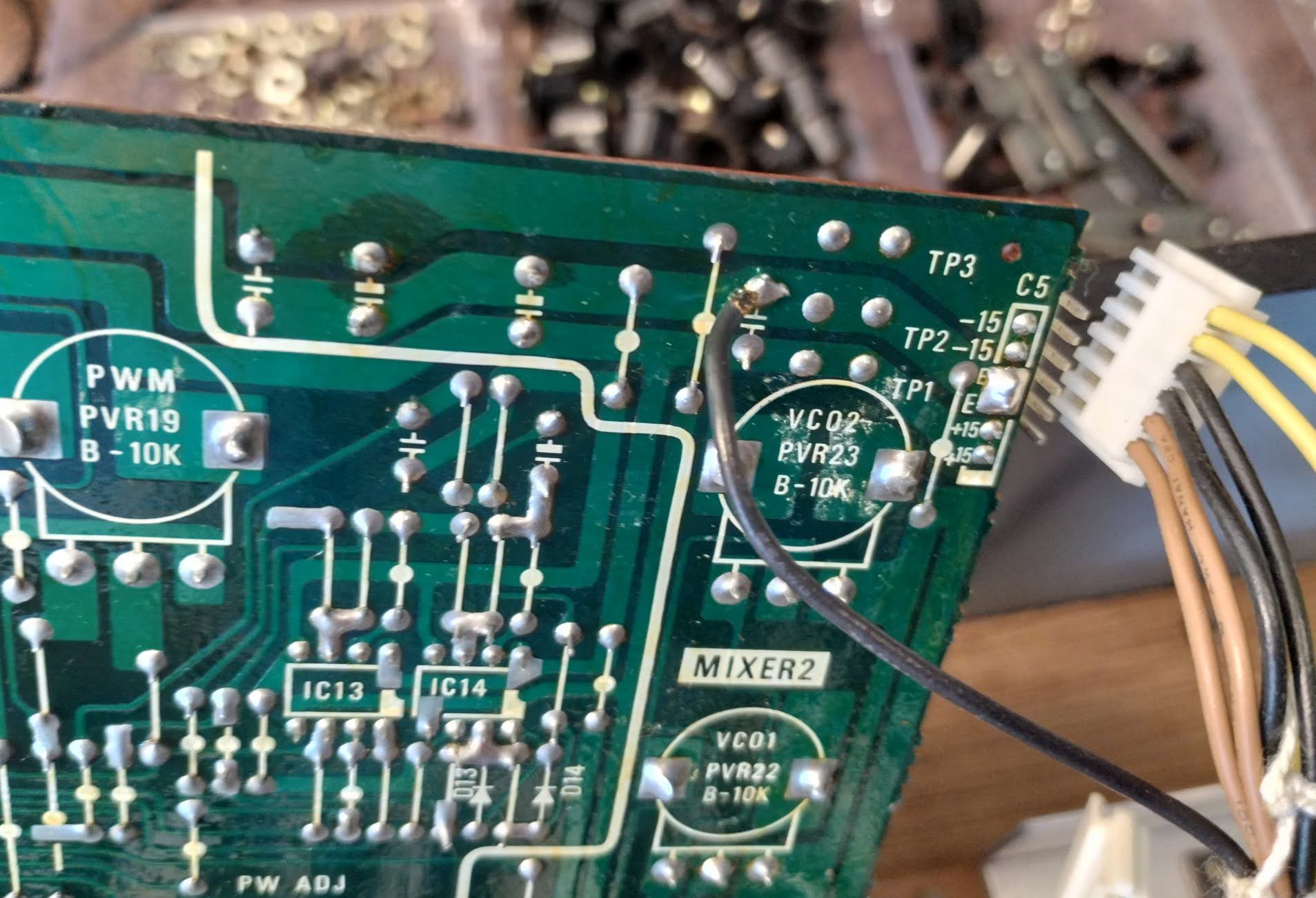
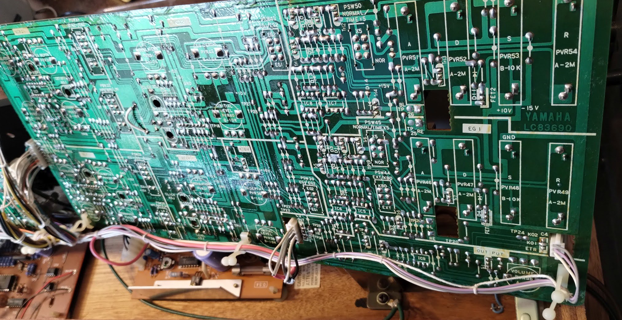
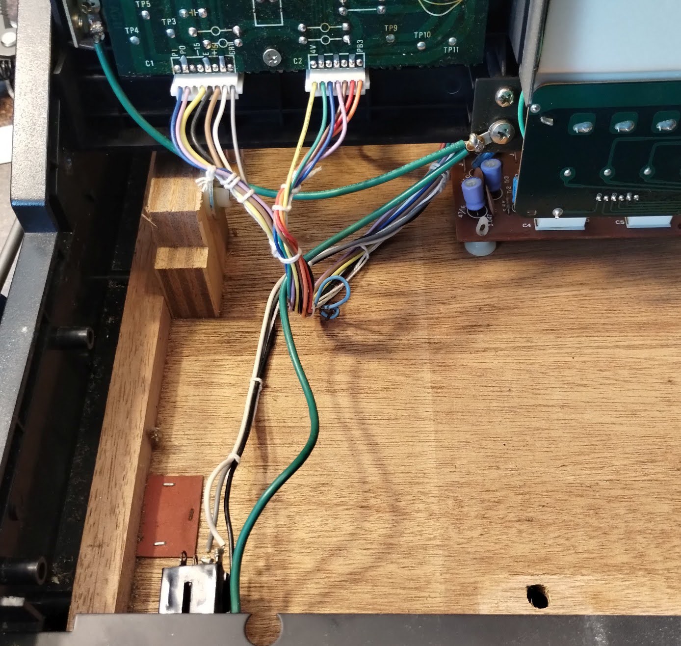
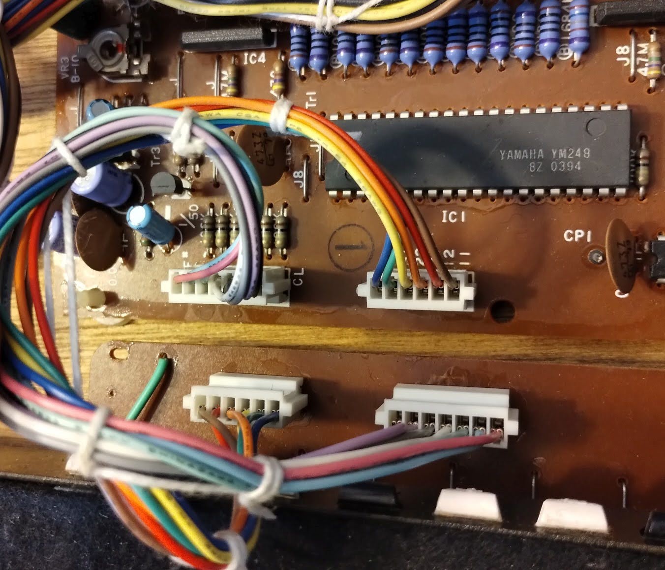
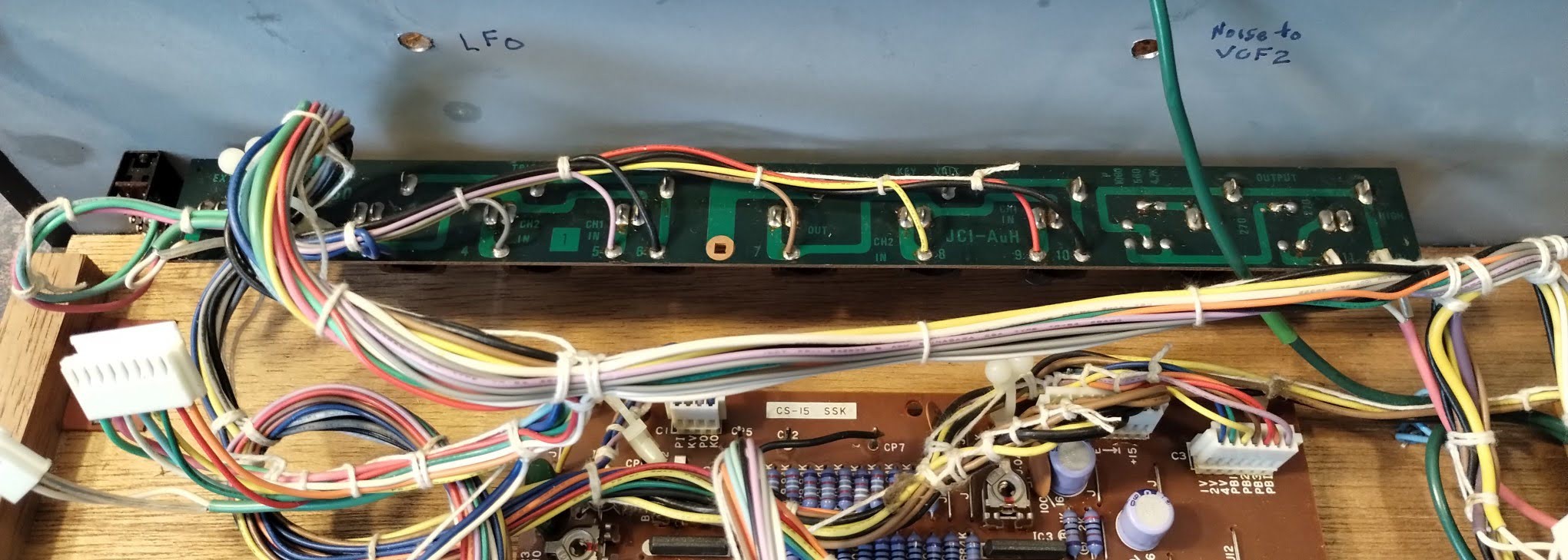
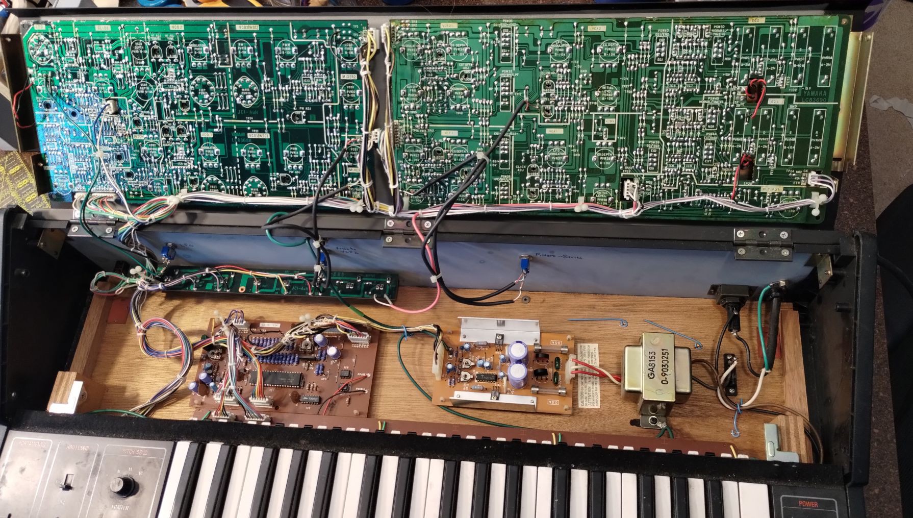
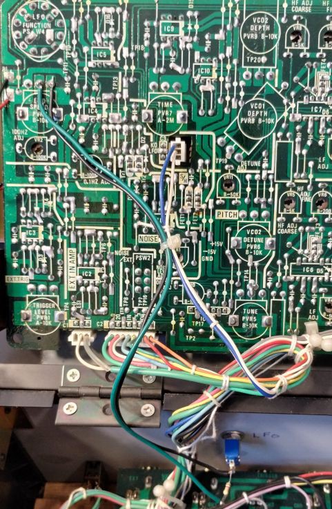
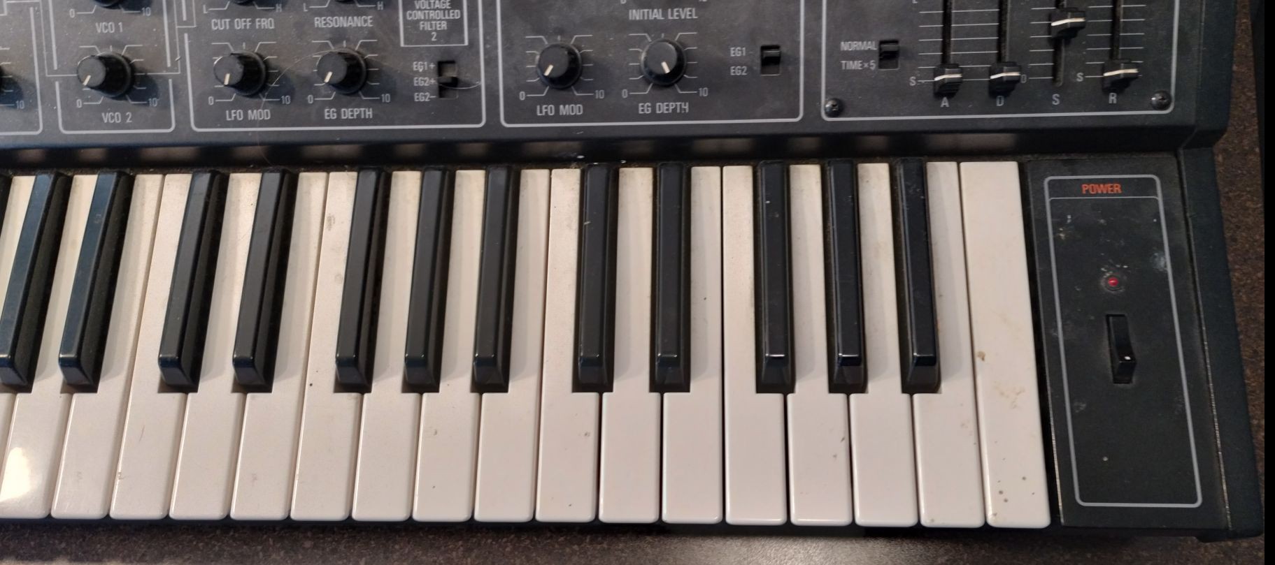
Yamaha CS-15
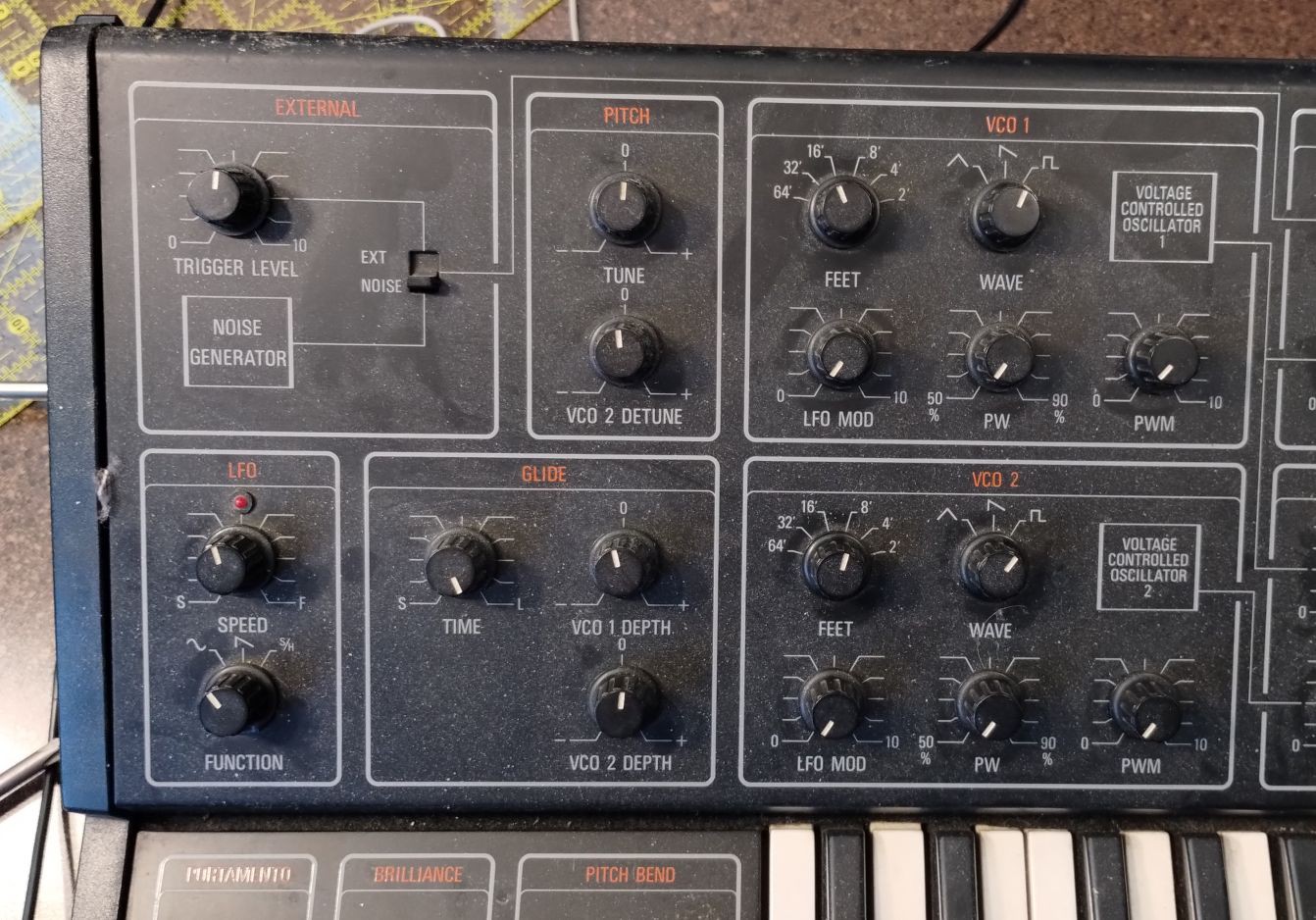
This is a classic monophonic analog subtractive synthesizer. It's sometimes refered to aa duophonic as it has two parallel chains which can be configured separately, but they are driven with the same CV/Trig from the keyboard so only one key can be played at a time. Using external inputs they can be driven separately.
(I've played a bunch with this, but will document later as I do restore and repair)
Project Logs
Ongoing logs:
- Initial Evaluation
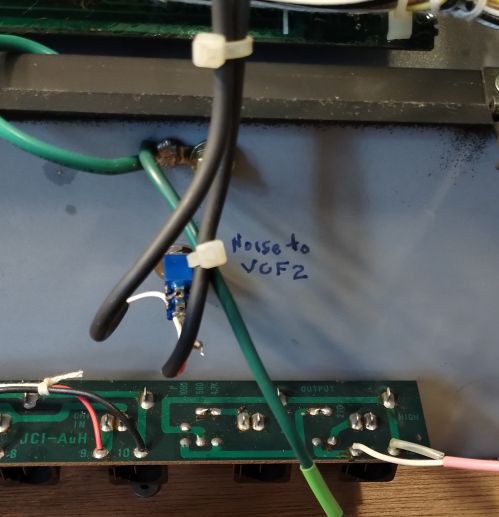
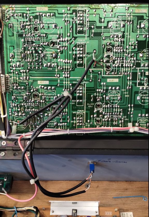
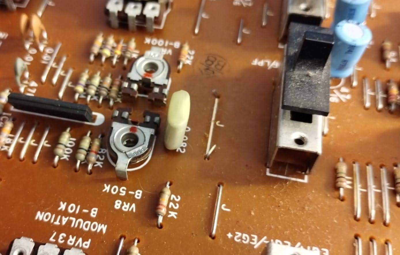
- Modification Analysis
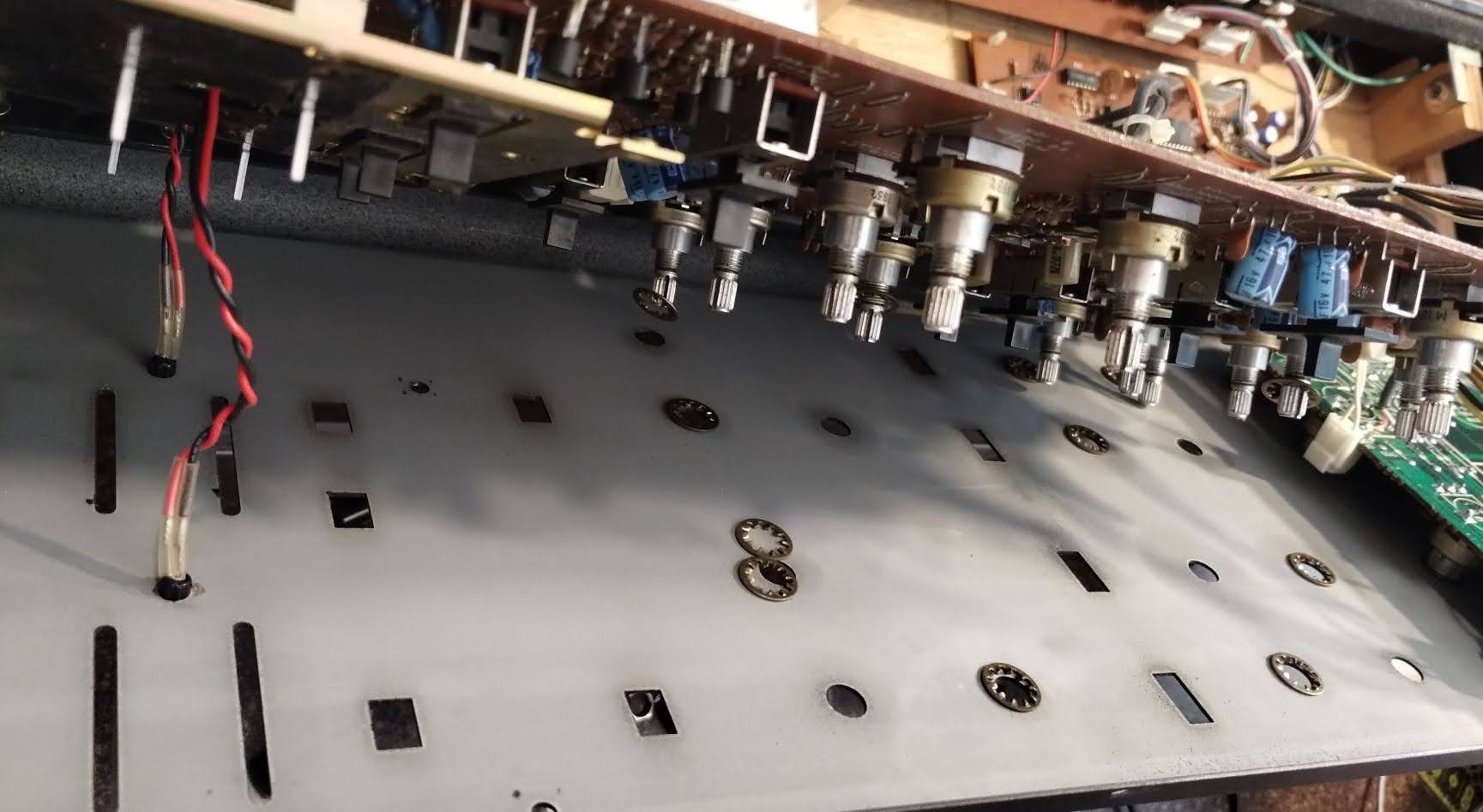
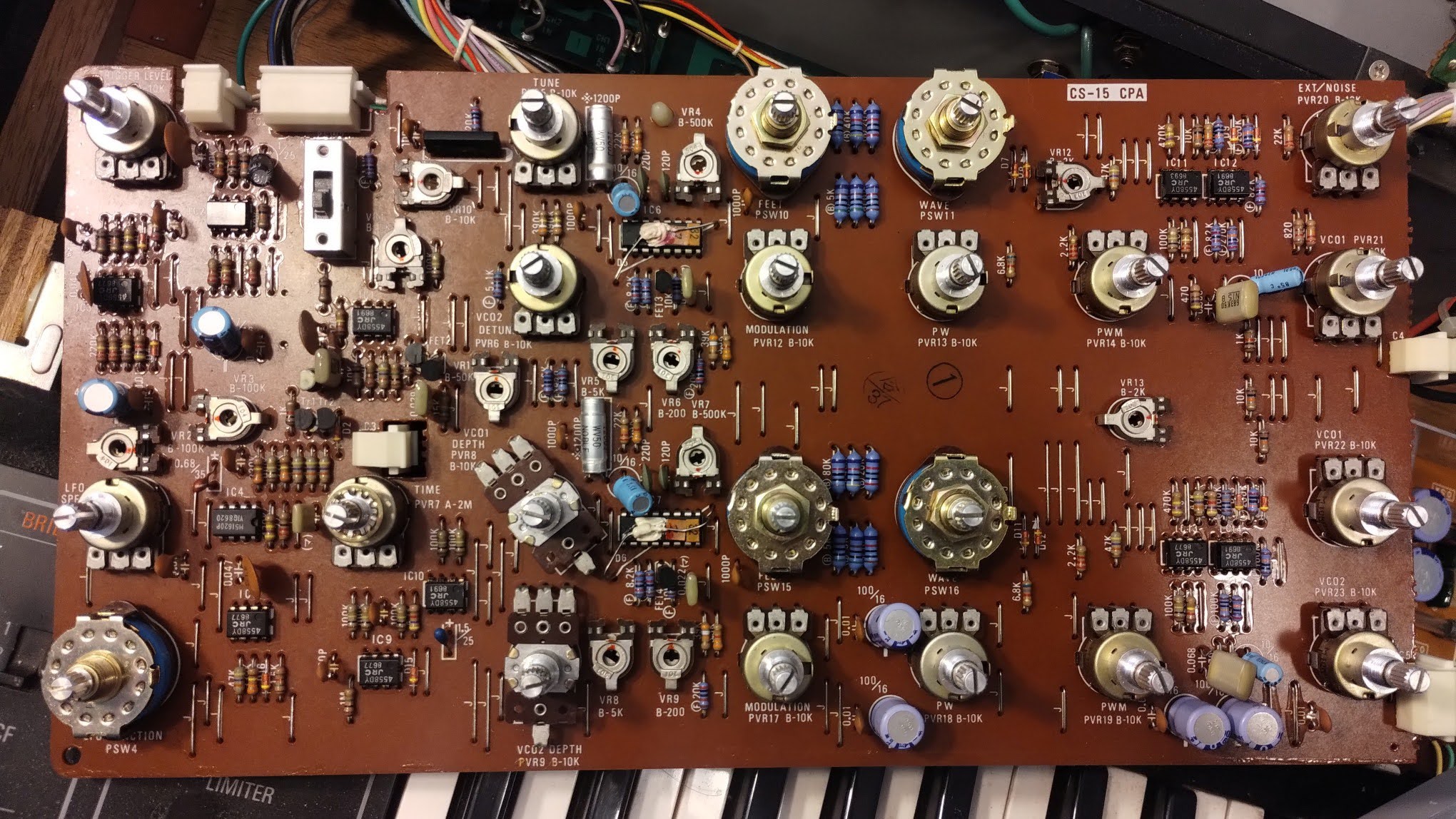
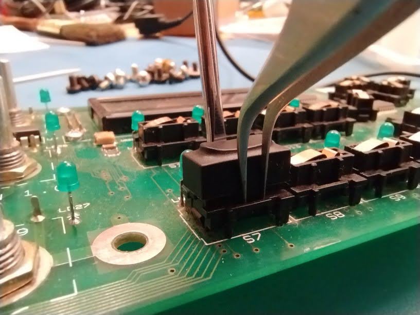
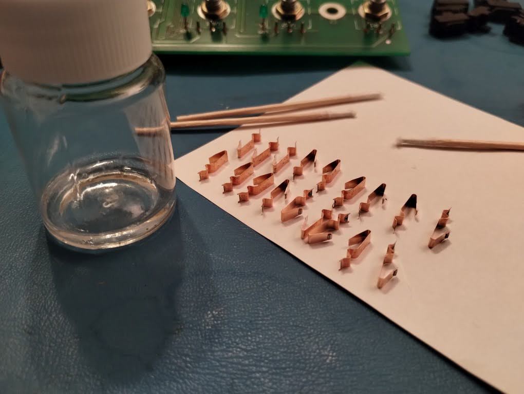
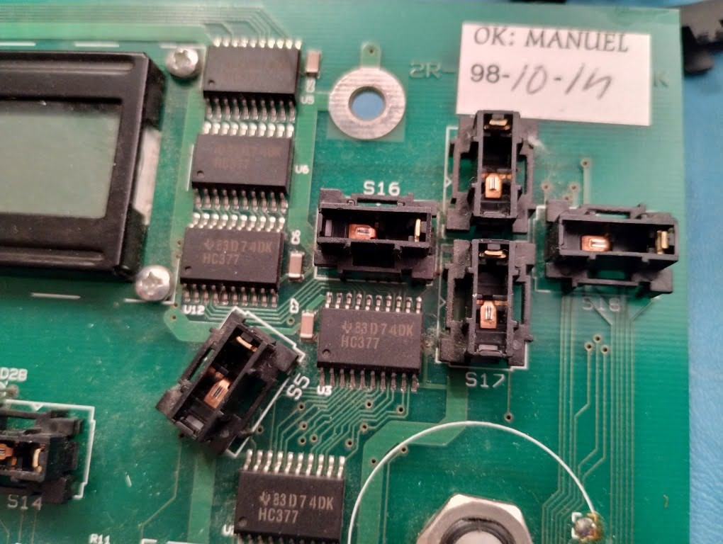
- Disassembly part 1
- Disassembly part 2, Keyboard (soon)


 Tina Belmont
 Emily Velasco
 Steve Smith