Now that I have the hardware the project is fun again and it's advancing much faster than I anticipated :).
I have tested the ATtiny85-20SU and ATtiny85V-10SU for power consumption in power-down more on the emitter, they're basically the same, so I can remove the technically more power efficient V-10SU-type from the parts list and use two 20SU-types.
At first I wanted to use the V-10SU-type because it can still reliably work at 1.8V, but I forgot that the transmitter also needs decent voltage to be able to emit something (it's actually rated between 3 and 12V), also the 3V coin-cell battery would be pretty much deceased at 1.8V, even with some remaining voltage when the transmission would begin the voltage would probably fall to 0, so two 20SU it is.
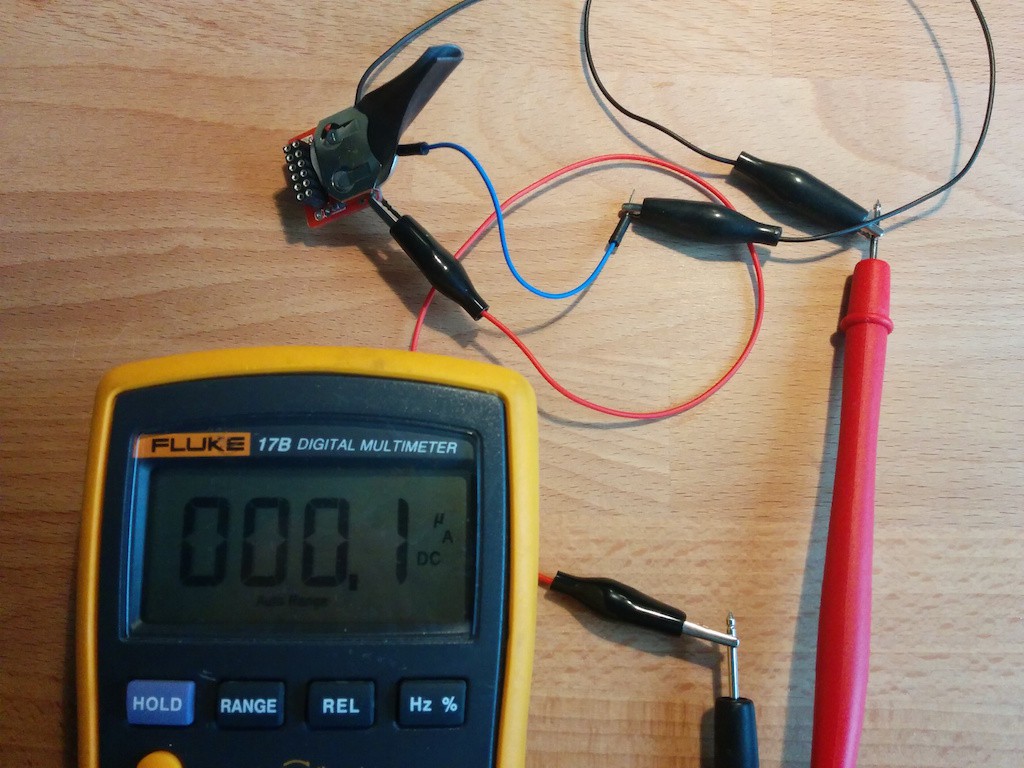
As written in the datasheet the ATtiny uses 0.1uA in power-down mode, that's what I measured, this is quite incredible and a 200mAh CR2032 battery would last 228 years! Now to be more realistic the transmission takes about 7mA for a fraction of a second which is not negligible, even if only about once per day and the weather conditions and battery self discharge also play a role in battery life. But my goal was 1 year of battery life and that's probably satisfied.
I have also implemented a one-minute waiting period after the message has been sent so that multiple messages, and thus excessive power, wouldn't be used when different things are inserted in the mailbox. In Switzerland, and Europe in general, the mailboxes usually have 2 compartments: one for the letters, closed with a key, with an lid that moves inside the mailbox and another one, for small packages, with a little door that opens outside. The mailman will drop the letters in the letter compartment one by one and will this trigger the system multiple times requiring this setup.
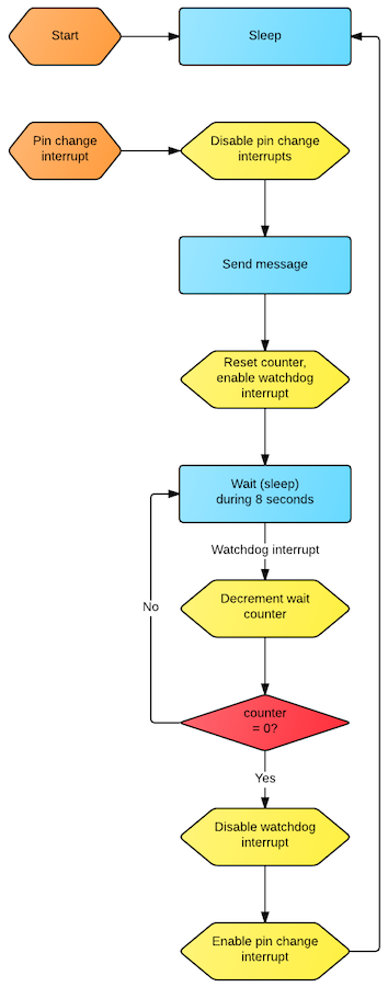
During this one-minute waiting period the MCU uses 4.3uA as it uses the watchdog that sleeps for 8 seconds, decrements a counter, and continues to sleep until 8s*8=64s have passed, then it disables the watchdog and returns to power-down mode (0.1uA). I drew a state machine of how the emitter works using Lucidchart:
 The reason to not use a reed or a light sensor is evident here: an active sensor needs power (>1mA), but why use an active sensor when a passive uses absolutely no power whatsoever? That's why a simple lever-switch is the best kind of "sensor" in this scenario.
Discussions
Become a Hackaday.io Member
Create an account to leave a comment. Already have an account? Log In.