I haven't updated this project for a long time, but that's because I've worked on it on the side whenever I had time and changed my mind a lot.
It has taken a bit of a turn: I have discovered V-USB/Digispark on the way and decided the receiver should be a stand-alone module as my receiver-connected-to-a-random-Arduino wasn't as elegant as I hoped. I bought some ATtiny85-20 and other passive parts to test them on a custom etched a circuit. I now have a fully functional USB receiver module that forwards data to a computer.

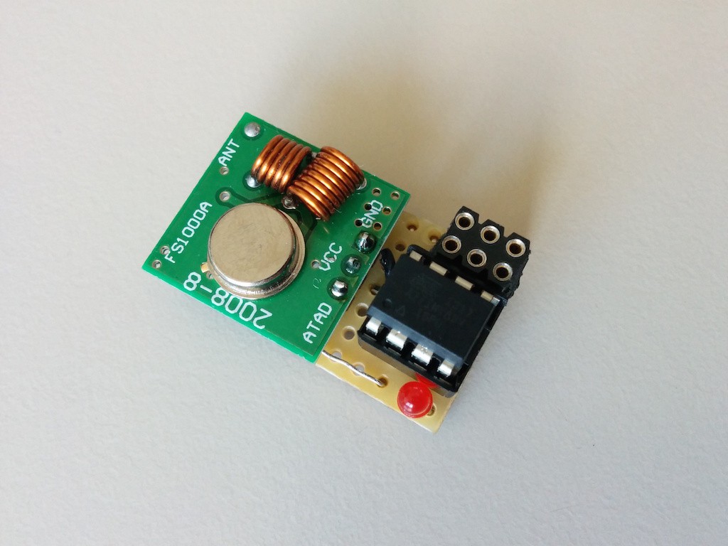
Early transmitter module on a stripboard with a DIP ATtiny85V-10 MCU.


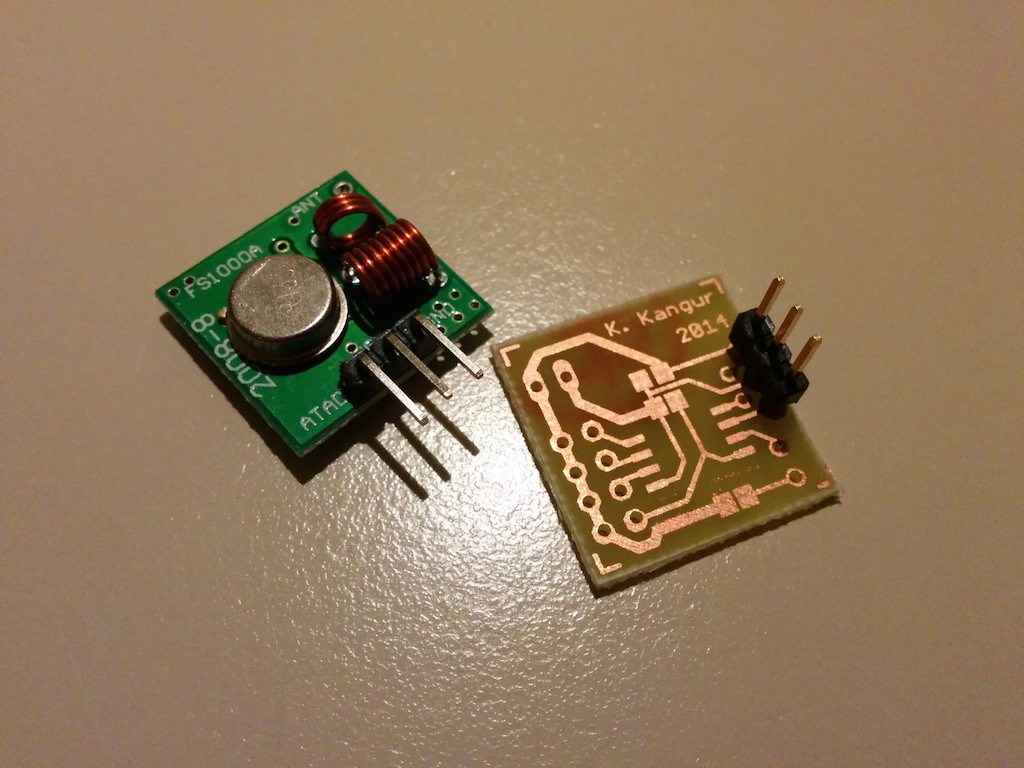
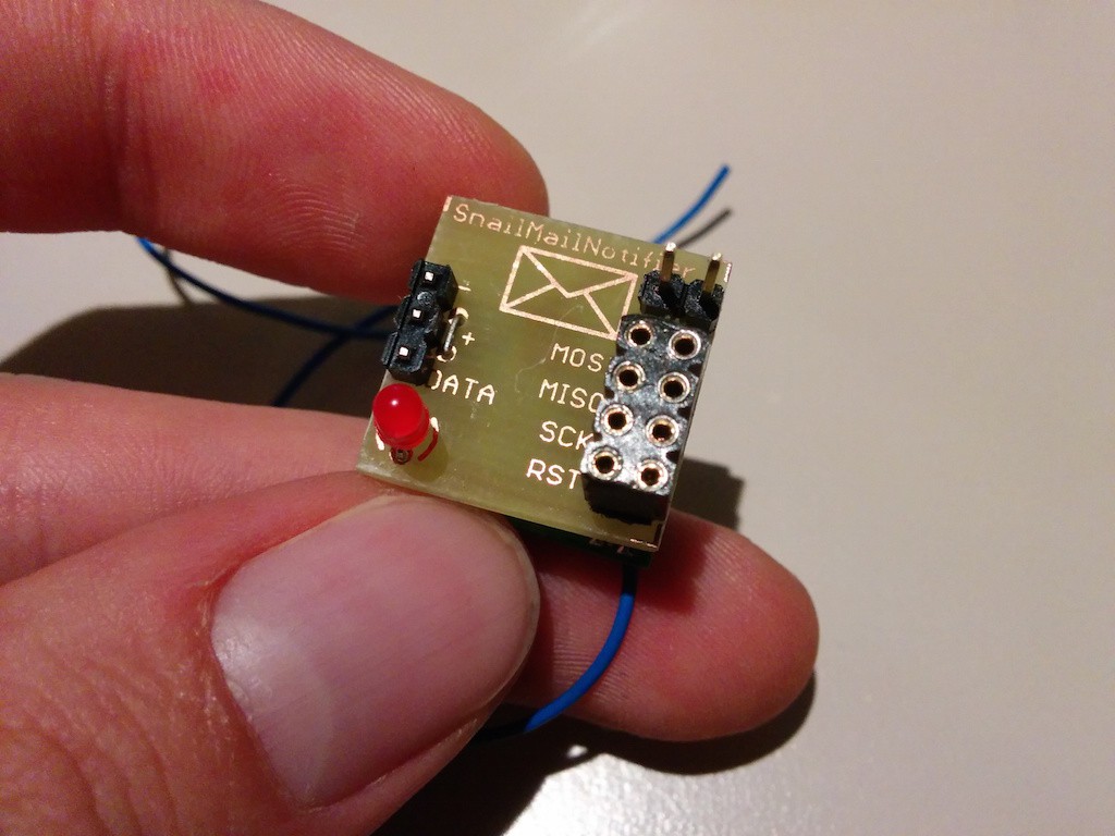
Current transmitter module on an etched PCB, the MCU can be reprogrammed via the broken out pins.

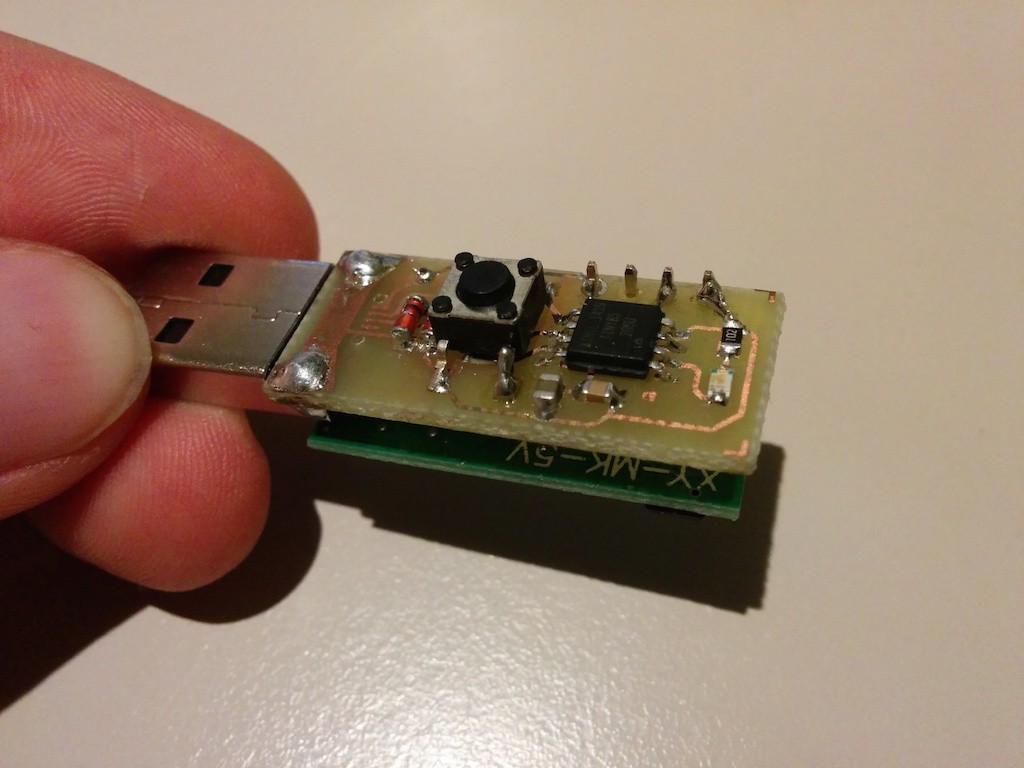
Receiver module with both USB-A and micro-USB connector footprints. I programmed the MCU via a temporarily soldered ISP connector, now it can be reprogrammed using the Digispark bootloader.
I will definately be using the cheap 433MHz transmitter/emitter pair mainly because of price, low power usage and virtually no voltage regulation requirements. The transmission is quite reliable.
Something that is a bit annoying currently is that I use a ATtiny85V-10 for the transmitter and an ATtiny85-20 for the receiver (because of USB), indeed the 85V version can function down to 1.8V, but I'm not sure it's really useful as I intend to power the transmitter via a 3V lithium button cell and also the transmission power being dependant on voltage this 1.8V "advantage" might make it absolutely useless.
I have measured the power consumption of the transmitter and it was only 100nA in power-down mode, also thanks to the transmitter module that doesn't consume any power whatsoever, contrary to NRF or RFM modules. The ATtiny85V-10 can work at 1MHz between 1.8 and 2.4V and up to 8MHz from 2.4 to 5V, when I tested it I could get reliable transmission with 8MHz at 1.7V, completely out of specifications :).
As far as software is concerned both modules work as expected: transmission, reception and forwarding to computer. The Atmel MCU can measure their own supply voltage and have an uncalibrated internal temperature sensor which I forward together with the actual data just because I can.
I'm about to order some PCBs for both sides to make the whole thing more elegant and professional looking. By the end of the project both sides will have a nice 3D printed enclosures.
Discussions
Become a Hackaday.io Member
Create an account to leave a comment. Already have an account? Log In.