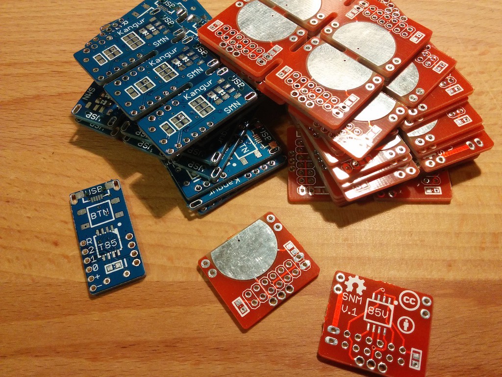
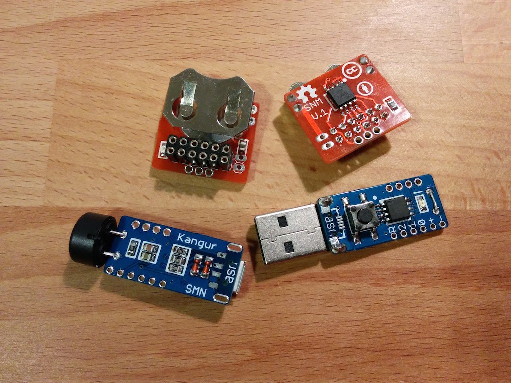
The PCBs arrived a while ago, but I didn't have the motivation to assemble and document right away. Now that they're assembled I started screwing around and programming all sorts of useless stuff... I'm not good without a deadline.

So far I have only tested the receiver board, without the receiver module. I routed the lines the same way as Digispark so that I wouldn't have to mess around with the Digispark libraries (that was quite annoying with my prototype boards), eventually this project should be easily reproducible so that's a plus.
I routed the passive buzzer, 1K current limiting resistor and LED in series, thinking that by toggling the pin slowly I could make the LED blink and when toggled fast the buzzer would make some noise, unfortunately the buzzer is a piezoelectronic type which means it's effectively an open circuit... why didn't I test it before >_<?!? The good news is that by mounting the buzzer OR the LED and shorting the missing element they work separately. Not as pretty as I would've wanted, but eh...
The receiver board works fine and looks quite good, the emitter hasn't been tested yet, but will be whenever I feel like it. On the emitter boards I soldered an ATtiny85-20SU on one and an ATtiny85V-10SU on the other to see how they perform power-wise when in power-down mode, maybe I could cut the V-10SU from the parts list and go with the 20SU-type on both sides. Since there are 2 types of footprints for the USB connector (uUSB and USB-A) I soldered one of each on the boards, the same with the buzzer/LED.
I think I'll have way too many boards left over so if anyone's interested...
Now I'll be slowly, on and off, working on the software side of the project for the next couple of months.
Discussions
Become a Hackaday.io Member
Create an account to leave a comment. Already have an account? Log In.