During this week's session, we continued our exploration on how to design a cam. To achieve this, we searched for YouTube videos to enhance our understanding. Specifically, the video attached below has proven immensely helpful, as it provided insights into selecting the appropriate RPM (revolutions per minute) for our project, as well as delving into technical concepts such as dwell. Dwell refers to "a slight regular pause in the motion of a machine." Furthermore, this video serves as a reference for potential calculations throughout the project development process, such as determining the duration of each cycle the cam will dwell in a certain position given a specific RPM (where rps = rpm/60 seconds), or calculating the time taken to complete one revolution (using the inverse of rotational velocity formula t = 1/w).
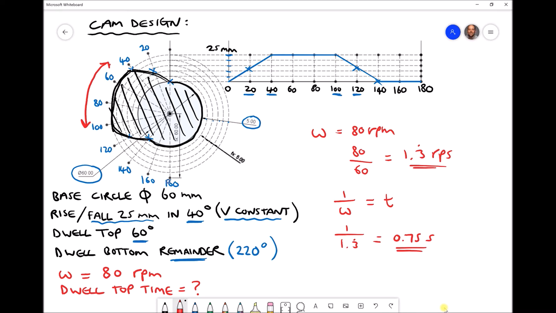
*Youtube video: Cam Design to Achieve a Specified Follower Motion. Link: Cam Design to Achieve a Specified Follower Motion (youtube.com)
Simultaneously, in this session, we endeavored to assemble the set of components required to build the clock. However, due to the precise millimetric design of these pieces, either due to their small size or issues stemming from 3D printing, this process presented challenges. As we assembled the clock, we noticed that the pieces lacked the necessary tolerances for easy fitting and assembly without compromising their integrity.
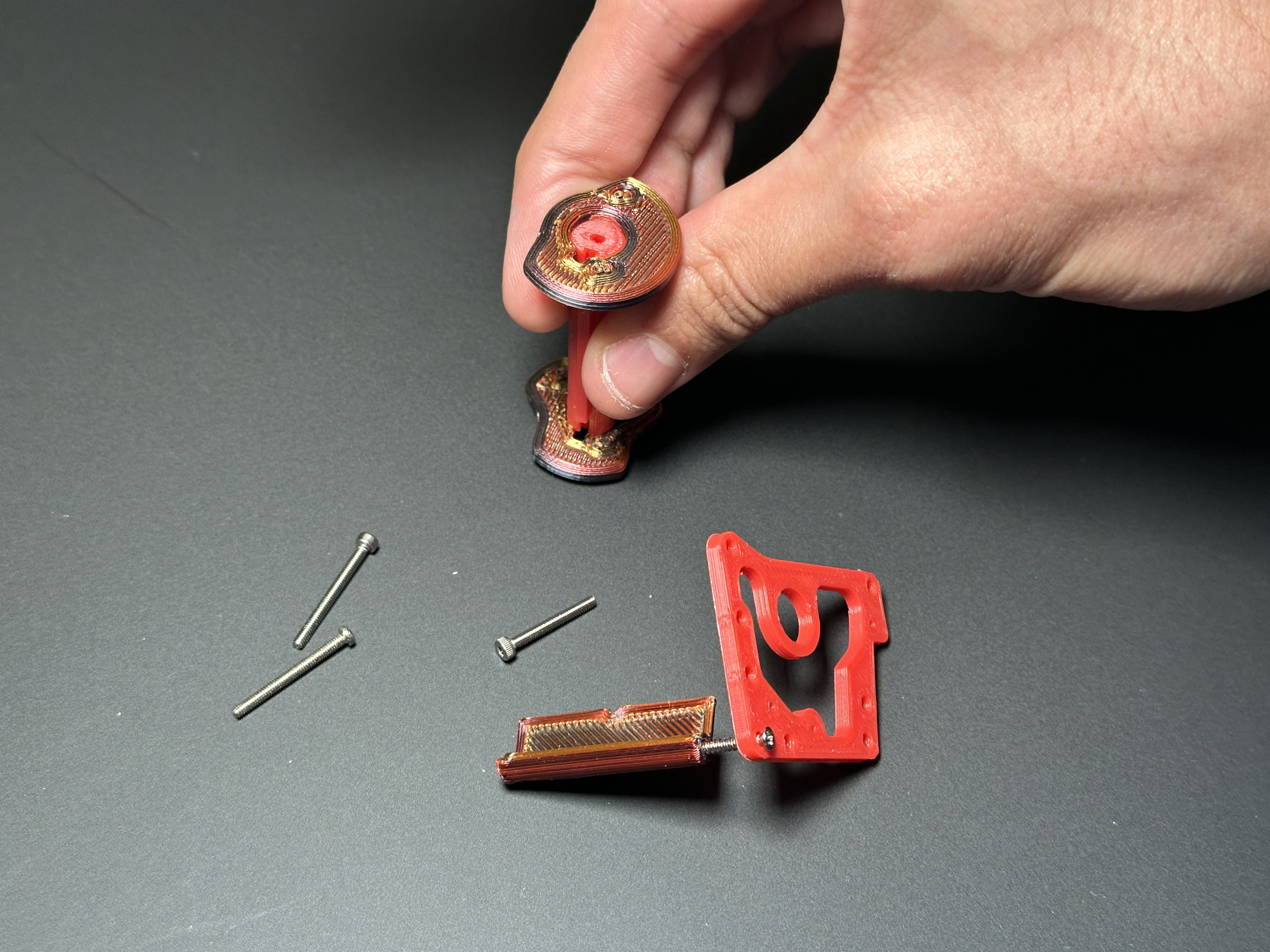
*Challenges when assembling the plastic parts.
Consequently, we made the decision to redirect our final product. It is important to acknowledge that the design process is iterative rather than linear; setbacks are part of the journey towards progress. Additionally, we identified that the fabrication of our initial clock prototype required overly complex electronic components. By simplifying our design process and replacing unnecessary components with more suitable alternatives, such as motors, we aim to streamline our workflow. As engineers, our mission is to seek solutions to the problems we encounter and provide optimal and efficient outcomes.
Moving forward, we are exploring alternative paths for our project. Below is a mood board featuring various product ideas that align with our project requirements.
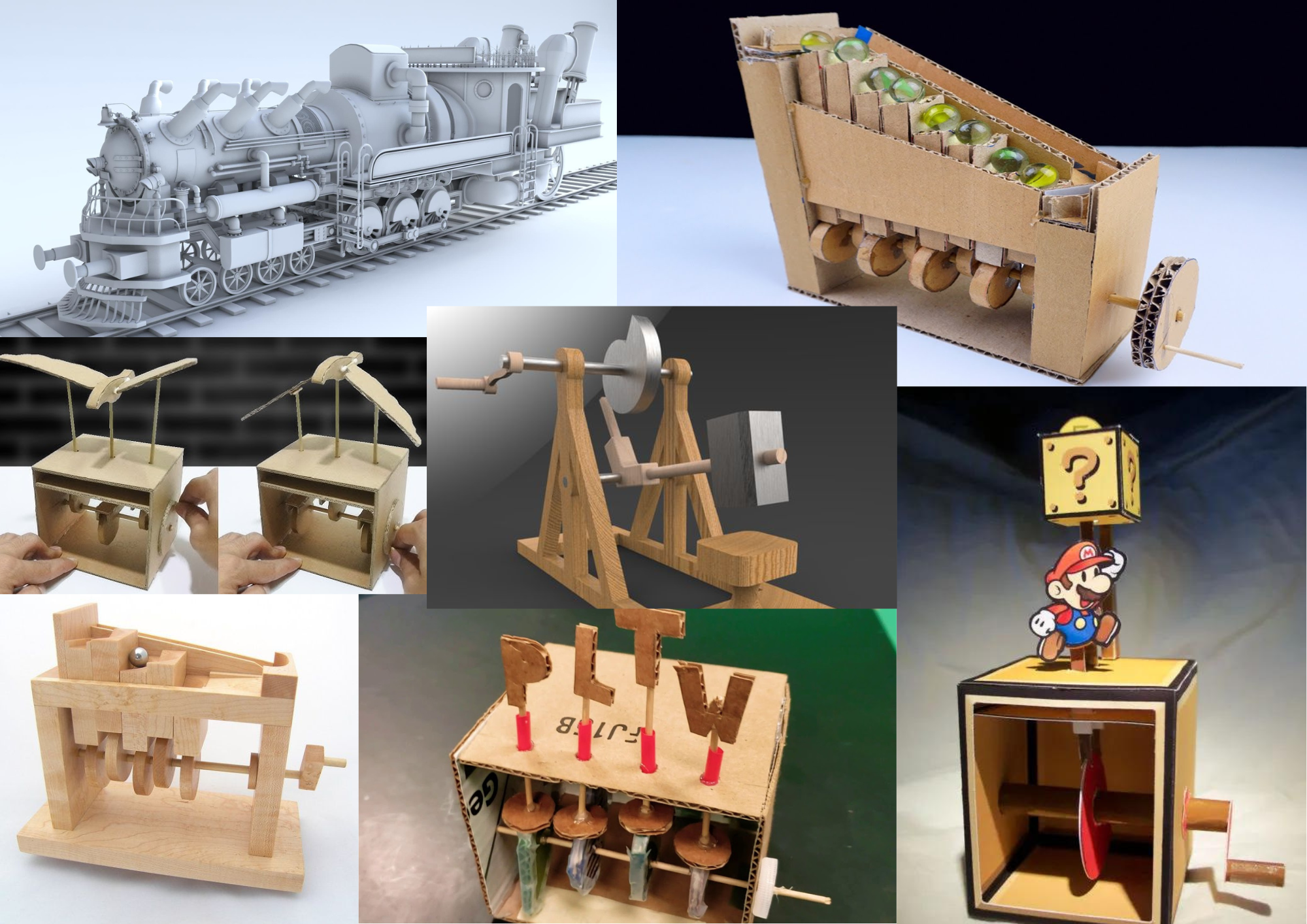
*Moodboard of new ideas using cam, cam followers and gears.
We remain committed to the success of our project and welcome any insights or suggestions that may contribute to its advancement.
Additionally, we carried out the Minimum Viable Product (MVP) of our project. To achieve this, we developed a new prototype in cardboard to put into practice what we learnt about t cams and how the mechanism operates. Specifically, we focused on simulating the movement of a butterfly.
While creating the cardboard prototype, we encountered several complications. However, these challenges provided us with insights, particularly regarding the necessity of increasing the distance between the cams. Furthermore, a problem we had is that the sticks connected to the wings and the body of the butterfly rotate instead of remaining stationary while only executing the movement of going up and down. We will address this issue in our next session.
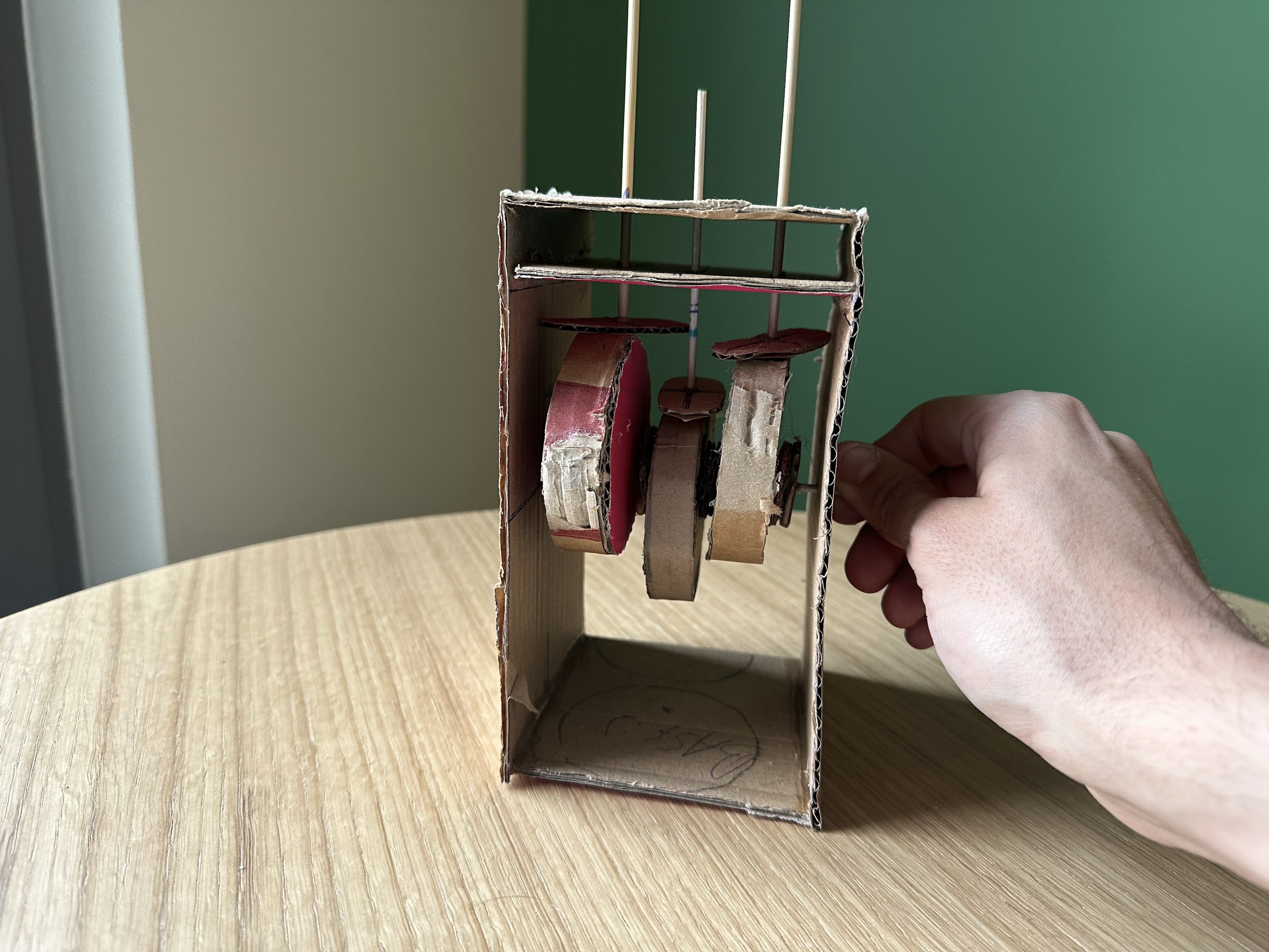
*Trying out how cams work are working before attaching the animal we want to move.
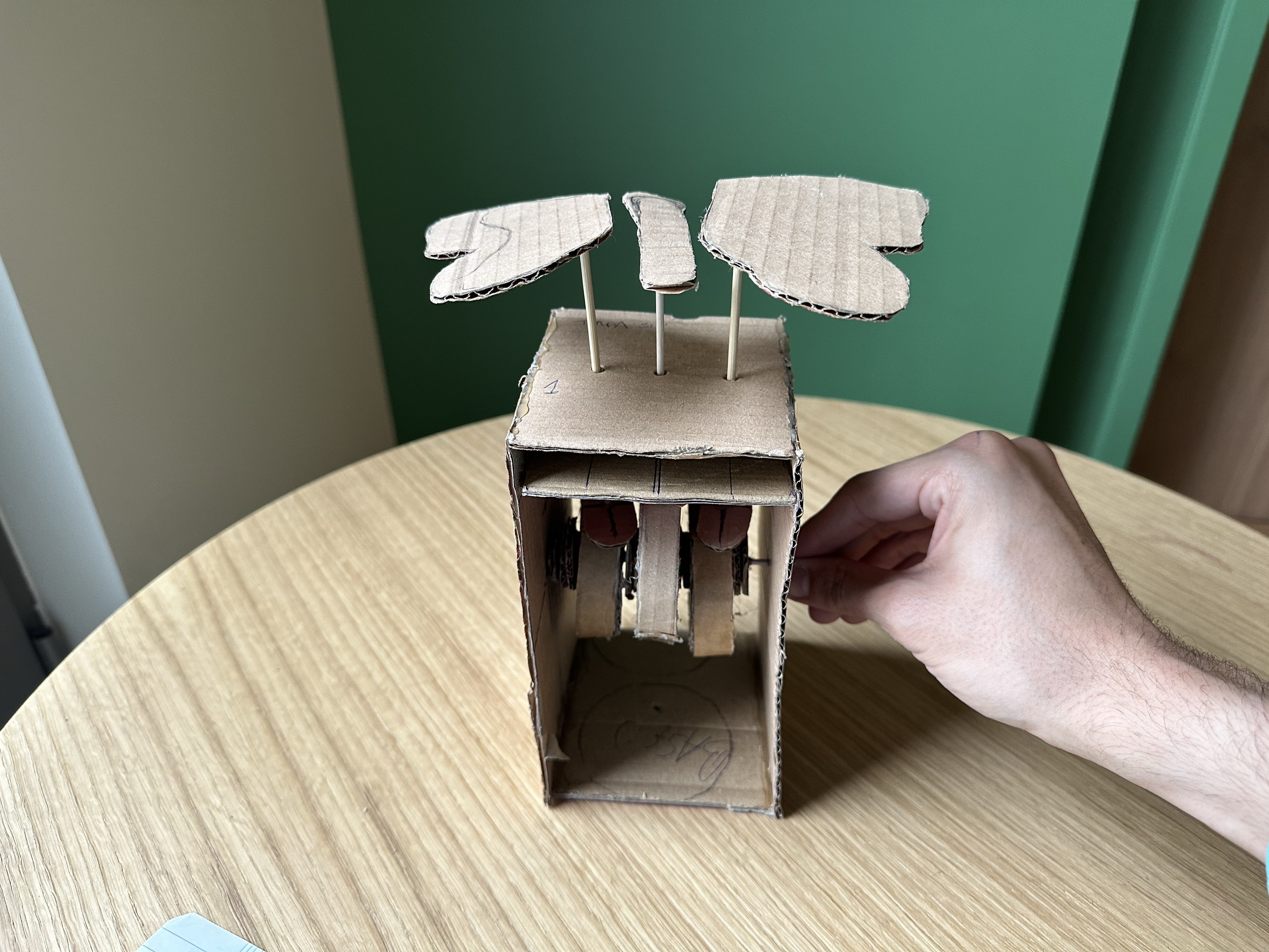
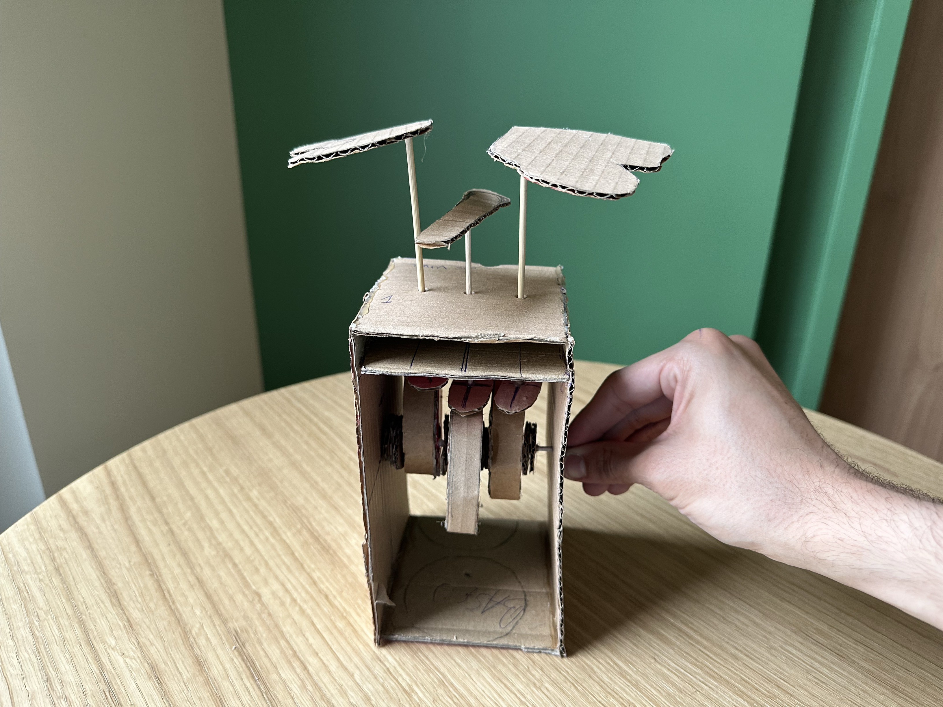
* Proving that the wings move according to the movement of the cams
 Bruno
Bruno *Trying out how cams work are working before attaching the animal we want to move.
Discussions
Become a Hackaday.io Member
Create an account to leave a comment. Already have an account? Log In.