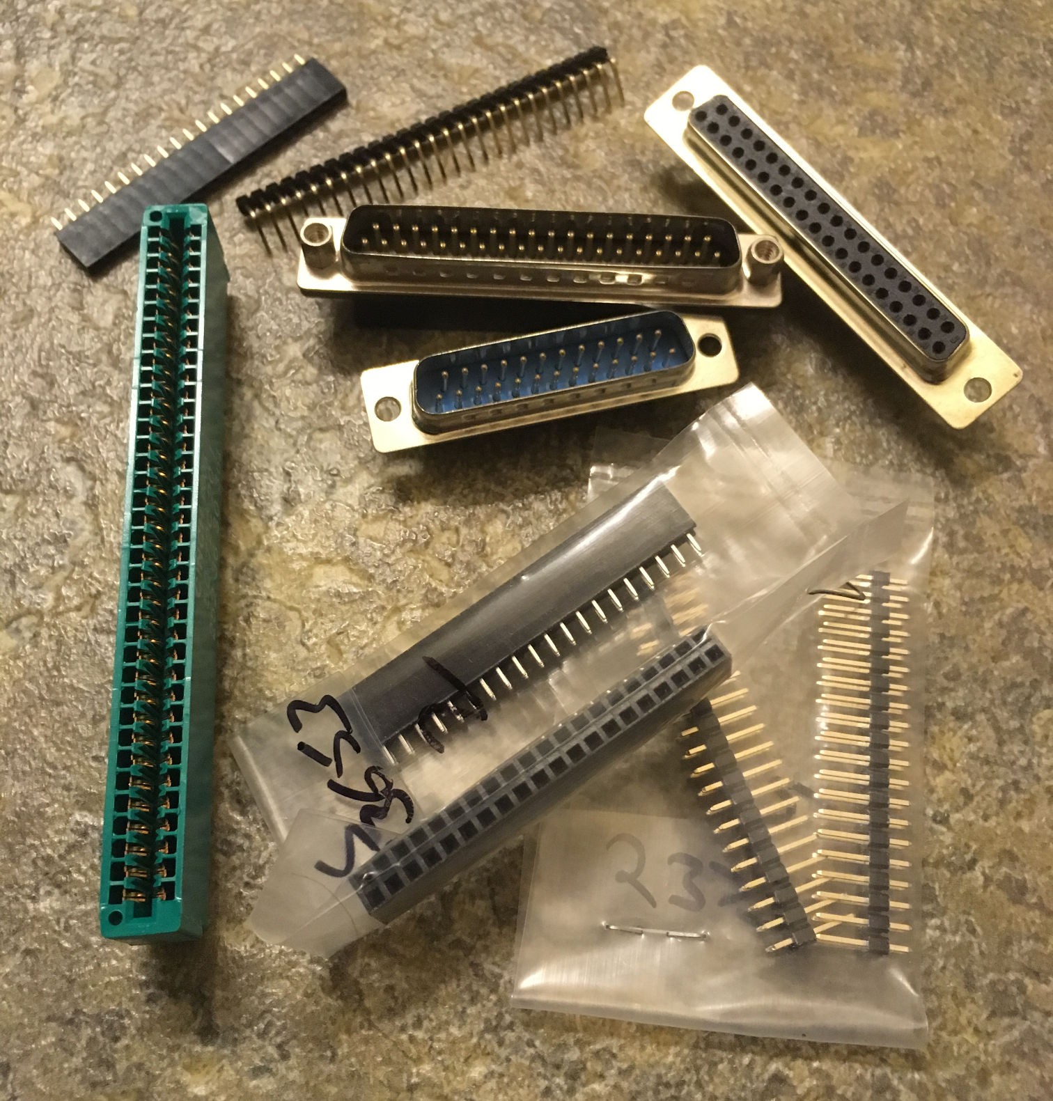
As you can see I plan to have 8K of external memory (like a cartridge or something) in the address range 0x6000...0x7FFF, so question is - what should it be physically? Connector must have 2 power signals (+5V and GND), 13 address signals (to cover 8K address range), 8 data signals and also 3 control signals: /CS, /RD, /WR, so total is 26.
Should it be 1 row of pins? 2 rows of pins? Male? Female? D-SUB connector? Edge connector? Or may be something else? Please share you thoughts in comments below! Thank you ;)

 SHAOS
SHAOS
Discussions
Become a Hackaday.io Member
Create an account to leave a comment. Already have an account? Log In.
Definitely the dual-row at the bottom, it's much more practical.
DBxx won't cut it (you'll also have to adapt between imperial and metric spacings) and card edge connectors are a PITA...
Are you sure? yes | no
Yea, I think about this similarly, but there is a problem it's 40 pins (the only one that could be currently found for less than $1) - so it will have some spare pins for future ;)
Are you sure? yes | no
Yeah that's a prob.... oh wait...
Anyway there is a standard width with 34 pins, which is a compromise (I have "some", gotten from eBay brokers). But 2×20 is great because 1) more grounds/powers and 2) use old PATA cables and connectors 3) also used by the latest Raspberry Pis
Are you sure? yes | no
I hate Pis :)
Are you sure? yes | no