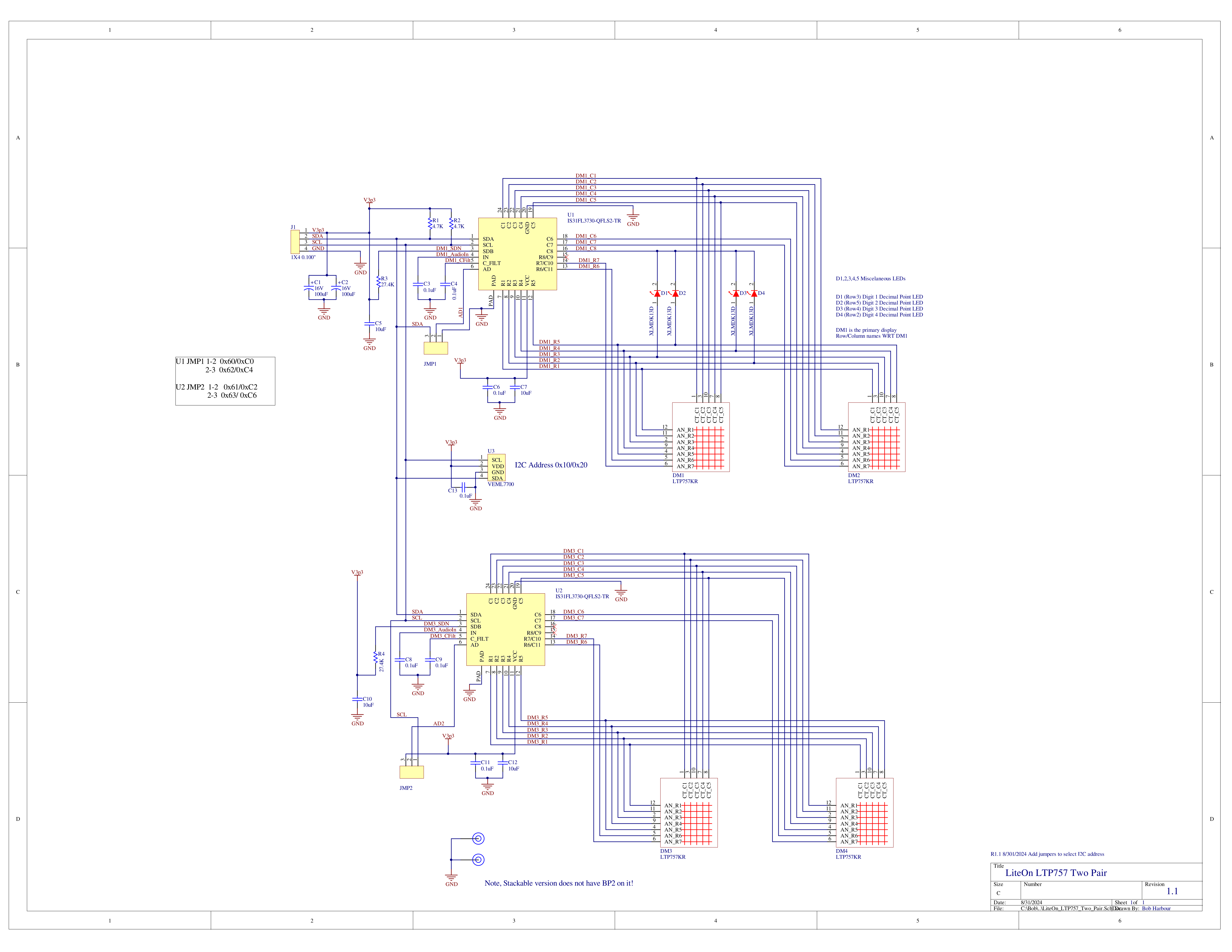
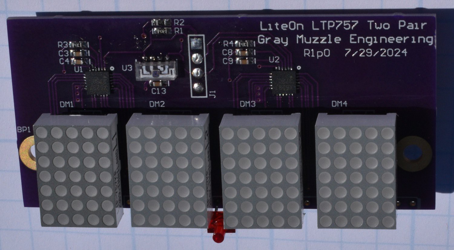
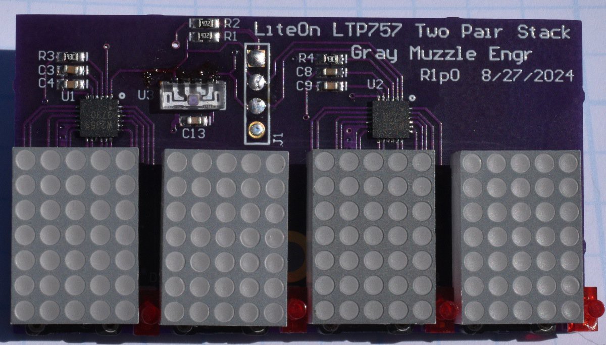
On the way through a long, hot, summer, I decided to lay out two variants of these displays. Neither of these boards was done with a specific project in mind. Both are 4 character boards built from the same schematic but have different mechanical setups.

The first board is designed to go into an application needing 4 alpha-numeric characters on a line. Maybe a meter or something similar. The second board is designed to be end to end stackable, so you can add characters in increments of 4 per board. Both boards have an ambient light sensor on them for auto-dimming the displays. Note that the auto-dimming is done in software.
There are two driver chips per board to support the 4 characters. Each chip can listen on 1 of 4 addresses, so an I2C address mux will be required in a system using more than 1 of these boards. On rev 1.0 of these boards, the addresses for both driver chips are hard wired, meaning you will need one mux channel per board. The week after I sent the boards out to OSH Park, it occurred to me that with a couple of 3 pad jumpers per board, I could get two of these boards on the same I2C bus or mux channel. That will be rev 1.1 of the boards.The schematic shown is rev 1.1 with the jumpers added.


I have added discrete LEDs between the characters to use as decimal points in numeric applications. On the stackable version of the board, the discrete LEDs are in line with the bottom row of pixels of each display. On testing this, it doesn't look good. The decimal point does not stand out from the numbers and looks more like a bug than a feature. On the non-stackable version, the discrete LEDs are below the displays and this looks much better.
Mounting for the non-stackable boards is done with a pair of machine screws that will thread into standoffs on the back side of the board. Mounting for the stackable version of the boards uses a single machine screw between the second and third character.
A right angle connector adjusted to be a little less than right angle provides the power and I2C bus connections for the boards.
 Bharbour
Discussions
Become a Hackaday.io Member
Create an account to leave a comment. Already have an account? Log In.